Arduino 开发
本章节包含以下部分,请按需阅读:
Arduino 入门教程
初次接触 Arduino ESP32 开发,想要快速上手?我们为您准备了一套通用的 入门教程。
- 第0节 认识 ESP32
- 第1节 安装和配置 Arduino IDE
- 第2节 Arduino 基础知识
- 第3节 数字输出/输入
- 第4节 模拟输入
- 第5节 脉冲宽度调制 (PWM)
- 第6节 串行通信 (UART)
- 第7节 I2C 通信
- 第8节 SPI 通信
- 第9节 Wi-Fi 基础用法
- 第10节 网页服务器
- 第11节 蓝牙 (Bluetooth)
- 第12节 LVGL 图形界面开发
- 第13节 综合项目
请注意:该教程使用 ESP32-S3-Zero 作为教学示例,所有硬件代码均基于其引脚布局。在动手实践前,建议您对照手中的开发板引脚图,确认引脚配置无误。
配置开发环境
1. 安装和配置 Arduino IDE
请参考 安装和配置 Arduino IDE 教程 下载安装 Arduino IDE 并添加 ESP32 支持。
2. 安装库
要运行示例,需要安装对应的库。示例代码使用 GFX Library for Arduino 库驱动 ST7789 显示屏
,并使用 Arduino_DriveBus 库驱动 CST816 触摸芯片。
可从 此链接 的 Arduino 目录中,下载 ESP32-C6-Touch-LCD-1.83 开发板的示例程序包。包内的 Arduino\libraries 目录已包含本教程所需的全部库文件。
| 库或文件名称 | 说明 | 版本 | 安装方式 |
|---|---|---|---|
| GFX Library for Arduino | ST7789 显示驱动图形库 | v1.6.0 | 通过库管理器或手动安装 |
| SensorLib | PCF85063、QMI8658 传感器驱动库 | v0.3.1 | 通过库管理器或手动安装 |
| XPowersLib | AXP2101驱动库 | v0.3.0 | 通过库管理器或手动安装 |
| lvgl | lvgl显示显示框架 | v8.4.0 | 通过库管理器或手动安装 |
| Arduino_DriveBus | I2C,触摸驱动库 | v1.0.1 | 手动安装 |
LVGL 及其驱动库的版本之间存在较强的依赖关系。例如,为 LVGL v8 编写的驱动可能不兼容 LVGL v9。为确保示例能够稳定复现,推荐使用上表列出的特定版本。混合使用不同版本的库可能导致编译失败或运行时异常。
安装步骤:
-
下载 示例程序包。
-
将其
Arduino\libraries目录下的所有文件夹(Arduino_DriveBus、GFX_Library_for_Arduino 等)复制到 Arduino 的库文件夹中。信息Arduino 库文件夹的路径通常是:
c:\Users\<用户名>\Documents\Arduino\libraries。也可以在 Arduino IDE 中通过 文件 > 首选项,查看“项目文件夹位置”来定位。库文件夹就是此路径下的
libraries文件夹。 -
其他安装方式请参考:Arduino 库管理教程。
3. 其他提示
ESP32-C6-Touch-LCD-1.83 需要选择及配置开发板。
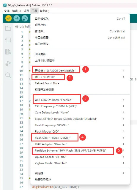
- ESP32-C6-Touch-LCD-1.83 需要选择ESP32C6 Dev Module。
- 选择USB端口
- ESP32-C6-Touch-LCD-1.83 使用 ESP32-C6 原生 USB 接口,而非 UART 转 USB。对于串口通信:
-
printf()函数可直接使用; -
若要使用
Serial.println()函数,需要额外配置:在 IDE 工具菜单中启用"USB CDC On Boot"选项,或在代码中声明 HWCDC 对象处理 USB 串口通信。
-
- 选择16MB flash
- 选择合适大小的分区表
示例程序
Arduino 示例程序位于 示例程序包 的 Arduino/examples 目录中。
| 示例程序 | 基础例程说明 | 依赖库 |
|---|---|---|
| 01_sd_test | 展示基本的挂载TF卡过程,读写文件测试 | |
| 02_audio_out | 播放MP3音频 | |
| 03_axp2101_example | 电源管理芯片AXP2101测试 | XPowersLib |
| 04_qmi8658_example | IMU qmi8658测试 | SensorLib |
| 05_pcf85063_example | RTC实时时钟PCF85063测试 | SensorLib |
| 06_gfx_helloworld | 一个简单的 ST7789 屏幕驱动示例 | GFX_Library_for_Arduino |
| 07_LVGL_Arduino | lvgl8.4示例程序 | SArduino_DriveBus,GFX_Library_for_Arduino ,lvgl |
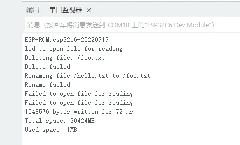
01_sd_test
本示例展示如何使用SPI挂载TF卡,并测试读写文件
代码
01_sd_test.ino
#include "FS.h"
#include "SD.h"
#include "SPI.h"


#define REASSIGN_PINS
int sck = 1;
int miso = 16;
int mosi = 2;
int cs = 17;

void listDir(fs::FS &fs, const char *dirname, uint8_t levels) {
  Serial.printf("Listing directory: %s\n", dirname);

  File root = fs.open(dirname);
  if (!root) {
    Serial.println("Failed to open directory");
    return;
  }
  if (!root.isDirectory()) {
    Serial.println("Not a directory");
    return;
  }

  File file = root.openNextFile();
  while (file) {
    if (file.isDirectory()) {
      Serial.print("  DIR : ");
      Serial.println(file.name());
      if (levels) {
        listDir(fs, file.path(), levels - 1);
      }
    } else {
      Serial.print("  FILE: ");
      Serial.print(file.name());
      Serial.print("  SIZE: ");
      Serial.println(file.size());
    }
    file = root.openNextFile();
  }
}

void createDir(fs::FS &fs, const char *path) {
  Serial.printf("Creating Dir: %s\n", path);
  if (fs.mkdir(path)) {
    Serial.println("Dir created");
  } else {
    Serial.println("mkdir failed");
  }
}

void removeDir(fs::FS &fs, const char *path) {
  Serial.printf("Removing Dir: %s\n", path);
  if (fs.rmdir(path)) {
    Serial.println("Dir removed");
  } else {
    Serial.println("rmdir failed");
  }
}

void readFile(fs::FS &fs, const char *path) {
  Serial.printf("Reading file: %s\n", path);

  File file = fs.open(path);
  if (!file) {
    Serial.println("Failed to open file for reading");
    return;
  }

  Serial.print("Read from file: ");
  while (file.available()) {
    Serial.write(file.read());
  }
  file.close();
}

void writeFile(fs::FS &fs, const char *path, const char *message) {
  Serial.printf("Writing file: %s\n", path);

  File file = fs.open(path, FILE_WRITE);
  if (!file) {
    Serial.println("Failed to open file for writing");
    return;
  }
  if (file.print(message)) {
    Serial.println("File written");
  } else {
    Serial.println("Write failed");
  }
  file.close();
}

void appendFile(fs::FS &fs, const char *path, const char *message) {
  Serial.printf("Appending to file: %s\n", path);

  File file = fs.open(path, FILE_APPEND);
  if (!file) {
    Serial.println("Failed to open file for appending");
    return;
  }
  if (file.print(message)) {
    Serial.println("Message appended");
  } else {
    Serial.println("Append failed");
  }
  file.close();
}

void renameFile(fs::FS &fs, const char *path1, const char *path2) {
  Serial.printf("Renaming file %s to %s\n", path1, path2);
  if (fs.rename(path1, path2)) {
    Serial.println("File renamed");
  } else {
    Serial.println("Rename failed");
  }
}

void deleteFile(fs::FS &fs, const char *path) {
  Serial.printf("Deleting file: %s\n", path);
  if (fs.remove(path)) {
    Serial.println("File deleted");
  } else {
    Serial.println("Delete failed");
  }
}

void testFileIO(fs::FS &fs, const char *path) {
  File file = fs.open(path);
  static uint8_t buf[512];
  size_t len = 0;
  uint32_t start = millis();
  uint32_t end = start;
  if (file) {
    len = file.size();
    size_t flen = len;
    start = millis();
    while (len) {
      size_t toRead = len;
      if (toRead > 512) {
        toRead = 512;
      }
      file.read(buf, toRead);
      len -= toRead;
    }
    end = millis() - start;
    Serial.printf("%u bytes read for %lu ms\n", flen, end);
    file.close();
  } else {
    Serial.println("Failed to open file for reading");
  }

  file = fs.open(path, FILE_WRITE);
  if (!file) {
    Serial.println("Failed to open file for writing");
    return;
  }

  size_t i;
  start = millis();
  for (i = 0; i < 2048; i++) {
    file.write(buf, 512);
  }
  end = millis() - start;
  Serial.printf("%u bytes written for %lu ms\n", 2048 * 512, end);
  file.close();
}

void setup() {
  Serial.begin(115200);

#ifdef REASSIGN_PINS
  SPI.begin(sck, miso, mosi, cs);
  if (!SD.begin(cs)) {
#else
  if (!SD.begin()) {
#endif
    Serial.println("Card Mount Failed");
    return;
  }
  uint8_t cardType = SD.cardType();

  if (cardType == CARD_NONE) {
    Serial.println("No SD card attached");
    return;
  }

  Serial.print("SD Card Type: ");
  if (cardType == CARD_MMC) {
    Serial.println("MMC");
  } else if (cardType == CARD_SD) {
    Serial.println("SDSC");
  } else if (cardType == CARD_SDHC) {
    Serial.println("SDHC");
  } else {
    Serial.println("UNKNOWN");
  }

  uint64_t cardSize = SD.cardSize() / (1024 * 1024);
  Serial.printf("SD Card Size: %lluMB\n", cardSize);

  listDir(SD, "/", 0);
  createDir(SD, "/mydir");
  listDir(SD, "/", 0);
  removeDir(SD, "/mydir");
  listDir(SD, "/", 2);
  writeFile(SD, "/hello.txt", "Hello ");
  appendFile(SD, "/hello.txt", "World!\n");
  readFile(SD, "/hello.txt");
  deleteFile(SD, "/foo.txt");
  renameFile(SD, "/hello.txt", "/foo.txt");
  readFile(SD, "/foo.txt");
  testFileIO(SD, "/test.txt");
  Serial.printf("Total space: %lluMB\n", SD.totalBytes() / (1024 * 1024));
  Serial.printf("Used space: %lluMB\n", SD.usedBytes() / (1024 * 1024));
}

void loop() {}
代码解释
-
初始化 SPI及挂载TF卡:
#ifdef REASSIGN_PINSSPI.begin(sck, miso, mosi, cs);if (!SD.begin(cs)) {#elseif (!SD.begin()) {#endifSerial.println("Card Mount Failed");return;}uint8_t cardType = SD.cardType();if (cardType == CARD_NONE) {Serial.println("No SD card attached");return;}Serial.print("SD Card Type: ");if (cardType == CARD_MMC) {Serial.println("MMC");} else if (cardType == CARD_SD) {Serial.println("SDSC");} else if (cardType == CARD_SDHC) {Serial.println("SDHC");} else {Serial.println("UNKNOWN");}uint64_t cardSize = SD.cardSize() / (1024 * 1024);Serial.printf("SD Card Size: %lluMB\n", cardSize); -
测试文件读写 :
listDir(SD, "/", 0);createDir(SD, "/mydir");listDir(SD, "/", 0);removeDir(SD, "/mydir");listDir(SD, "/", 2);writeFile(SD, "/hello.txt", "Hello ");appendFile(SD, "/hello.txt", "World!\n");readFile(SD, "/hello.txt");deleteFile(SD, "/foo.txt");renameFile(SD, "/hello.txt", "/foo.txt");readFile(SD, "/foo.txt");testFileIO(SD, "/test.txt");Serial.printf("Total space: %lluMB\n", SD.totalBytes() / (1024 * 1024));Serial.printf("Used space: %lluMB\n", SD.usedBytes() / (1024 * 1024));
02_audio_out
本示例演示如何使用 I2S播放音频,此例程屏幕无任何显示,烧录后会自动播放音频
代码
02_audio_out.ino
#include <Arduino.h>
#include "ESP_I2S.h"

#include "esp_check.h"

#include "Wire.h"
#include "es8311.h"

#include "music.h"

#define I2C_SDA 7
#define I2C_SCL 8

#define I2S_NUM I2S_NUM_0
#define I2S_MCK_PIN 19
#define I2S_BCK_PIN 20
#define I2S_LRCK_PIN 22
#define I2S_DOUT_PIN 23
#define I2S_DIN_PIN 21
#define PA_CTRL_PIN 0

#define EXAMPLE_SAMPLE_RATE (24000)
#define EXAMPLE_MCLK_MULTIPLE (256)  // If not using 24-bit data width, 256 should be enough
#define EXAMPLE_MCLK_FREQ_HZ (EXAMPLE_SAMPLE_RATE * EXAMPLE_MCLK_MULTIPLE)
#define EXAMPLE_VOICE_VOLUME (50)

I2SClass i2s;

void setupI2S() {
  i2s.setPins(I2S_BCK_PIN, I2S_LRCK_PIN, I2S_DOUT_PIN, I2S_DIN_PIN, I2S_MCK_PIN);
  // Initialize the I2S bus in standard mode
  if (!i2s.begin(I2S_MODE_STD, EXAMPLE_SAMPLE_RATE, I2S_DATA_BIT_WIDTH_16BIT, I2S_SLOT_MODE_MONO, I2S_STD_SLOT_LEFT)) {
    Serial.println("Failed to initialize I2S bus!");
    return;
  }
}

static esp_err_t es8311_codec_init(void) {
  es8311_handle_t es_handle = es8311_create(I2C_NUM_0, ES8311_ADDRRES_0);
  ESP_RETURN_ON_FALSE(es_handle, ESP_FAIL, TAG, "es8311 create failed");
  const es8311_clock_config_t es_clk = {
    .mclk_inverted = false,
    .sclk_inverted = false,
    .mclk_from_mclk_pin = true,
    .mclk_frequency = EXAMPLE_MCLK_FREQ_HZ,
    .sample_frequency = EXAMPLE_SAMPLE_RATE
  };

  ESP_ERROR_CHECK(es8311_init(es_handle, &es_clk, ES8311_RESOLUTION_16, ES8311_RESOLUTION_16));
  ESP_RETURN_ON_ERROR(es8311_voice_volume_set(es_handle, EXAMPLE_VOICE_VOLUME, NULL), TAG, "set es8311 volume failed");
  ESP_RETURN_ON_ERROR(es8311_microphone_config(es_handle, false), TAG, "set es8311 microphone failed");

  return ESP_OK;
}

void setup() {

  Serial.begin(115200);
  Wire.begin(I2C_SDA, I2C_SCL);
  es8311_codec_init();

  setupI2S();
  Serial.println("I2S Initialized");
  pinMode(PA_CTRL_PIN, OUTPUT);
  digitalWrite(PA_CTRL_PIN, HIGH);
}

void loop() {
  i2s.write((uint8_t *)audio_data, AUDIO_SAMPLES * 2);
}
代码解释
-
初始化I2C,I2S等外设,并配置ES8311解码器 :
Serial.begin(115200);Wire.begin(I2C_SDA, I2C_SCL);es8311_codec_init();setupI2S();Serial.println("I2S Initialized");pinMode(PA_CTRL_PIN, OUTPUT);digitalWrite(PA_CTRL_PIN, HIGH);
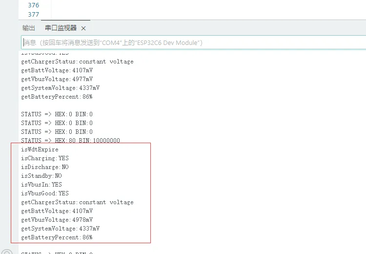
03_axp2101_example
本示例展示如何使用电源管理芯片,并打印出电池相关信息
代码
03_axp2101_example.ino
#define XPOWERS_CHIP_AXP2101

#include <Wire.h>
#include <Arduino.h>
#include "XPowersLib.h"

#ifndef CONFIG_PMU_SDA
#define CONFIG_PMU_SDA 7
#endif

#ifndef CONFIG_PMU_SCL
#define CONFIG_PMU_SCL 8
#endif

#ifndef CONFIG_PMU_IRQ
#define CONFIG_PMU_IRQ -1
#endif

bool  pmu_flag = 0;
XPowersPMU power;

const uint8_t i2c_sda = CONFIG_PMU_SDA;
const uint8_t i2c_scl = CONFIG_PMU_SCL;
const uint8_t pmu_irq_pin = CONFIG_PMU_IRQ;

void setFlag(void)
{
    pmu_flag = true;
}


void setup()
{
    Serial.begin(115200);
    delay(1000);
    bool result = power.begin(Wire, AXP2101_SLAVE_ADDRESS, i2c_sda, i2c_scl);

    if (result == false) {
        Serial.println("power is not online..."); while (1)delay(50);
    }

    Serial.printf("getID:0x%x\n", power.getChipID());

    // Set the minimum common working voltage of the PMU VBUS input,
    // below this value will turn off the PMU
    power.setVbusVoltageLimit(XPOWERS_AXP2101_VBUS_VOL_LIM_4V36);

    // Set the maximum current of the PMU VBUS input,
    // higher than this value will turn off the PMU
    power.setVbusCurrentLimit(XPOWERS_AXP2101_VBUS_CUR_LIM_1500MA);


    // Get the VSYS shutdown voltage
    uint16_t vol = power.getSysPowerDownVoltage();
    Serial.printf("->  getSysPowerDownVoltage:%u\n", vol);

    // Set VSY off voltage as 2600mV , Adjustment range 2600mV ~ 3300mV
    power.setSysPowerDownVoltage(2600);

    vol = power.getSysPowerDownVoltage();
    Serial.printf("->  getSysPowerDownVoltage:%u\n", vol);


    // DC1 IMAX=2A
    // 1500~3400mV,100mV/step,20steps
    power.setDC1Voltage(3300);
    Serial.printf("DC1  : %s   Voltage:%u mV \n",  power.isEnableDC1()  ? "+" : "-", power.getDC1Voltage());

    // DC2 IMAX=2A
    // 500~1200mV  10mV/step,71steps
    // 1220~1540mV 20mV/step,17steps
    power.setDC2Voltage(1000);
    Serial.printf("DC2  : %s   Voltage:%u mV \n",  power.isEnableDC2()  ? "+" : "-", power.getDC2Voltage());

    // DC3 IMAX = 2A
    // 500~1200mV,10mV/step,71steps
    // 1220~1540mV,20mV/step,17steps
    // 1600~3400mV,100mV/step,19steps
    power.setDC3Voltage(3300);
    Serial.printf("DC3  : %s   Voltage:%u mV \n",  power.isEnableDC3()  ? "+" : "-", power.getDC3Voltage());

    // DCDC4 IMAX=1.5A
    // 500~1200mV,10mV/step,71steps
    // 1220~1840mV,20mV/step,32steps
    power.setDC4Voltage(1000);
    Serial.printf("DC4  : %s   Voltage:%u mV \n",  power.isEnableDC4()  ? "+" : "-", power.getDC4Voltage());

    // DC5 IMAX=2A
    // 1200mV
    // 1400~3700mV,100mV/step,24steps
    power.setDC5Voltage(3300);
    Serial.printf("DC5  : %s   Voltage:%u mV \n",  power.isEnableDC5()  ? "+" : "-", power.getDC5Voltage());

    //ALDO1 IMAX=300mA
    //500~3500mV, 100mV/step,31steps
    power.setALDO1Voltage(3300);

    //ALDO2 IMAX=300mA
    //500~3500mV, 100mV/step,31steps
    power.setALDO2Voltage(3300);

    //ALDO3 IMAX=300mA
    //500~3500mV, 100mV/step,31steps
    power.setALDO3Voltage(3300);

    //ALDO4 IMAX=300mA
    //500~3500mV, 100mV/step,31steps
    power.setALDO4Voltage(3300);

    //BLDO1 IMAX=300mA
    //500~3500mV, 100mV/step,31steps
    power.setBLDO1Voltage(3300);

    //BLDO2 IMAX=300mA
    //500~3500mV, 100mV/step,31steps
    power.setBLDO2Voltage(3300);

    //CPUSLDO IMAX=30mA
    //500~1400mV,50mV/step,19steps
    power.setCPUSLDOVoltage(1000);

    //DLDO1 IMAX=300mA
    //500~3400mV, 100mV/step,29steps
    power.setDLDO1Voltage(3300);

    //DLDO2 IMAX=300mA
    //500~1400mV, 50mV/step,2steps
    power.setDLDO2Voltage(3300);


    // power.enableDC1();
    power.disableDC2();
    power.disableDC3();
    power.disableDC4();
    power.disableDC5();
    power.enableALDO1();
    power.disableALDO2();
    power.disableALDO3();
    power.disableALDO4();
    power.disableBLDO1();
    power.disableBLDO2();
    power.disableCPUSLDO();
    power.disableDLDO1();
    power.disableDLDO2();


    Serial.println("DCDC=======================================================================");
    Serial.printf("DC1  : %s   Voltage:%u mV \n",  power.isEnableDC1()  ? "+" : "-", power.getDC1Voltage());
    Serial.printf("DC2  : %s   Voltage:%u mV \n",  power.isEnableDC2()  ? "+" : "-", power.getDC2Voltage());
    Serial.printf("DC3  : %s   Voltage:%u mV \n",  power.isEnableDC3()  ? "+" : "-", power.getDC3Voltage());
    Serial.printf("DC4  : %s   Voltage:%u mV \n",  power.isEnableDC4()  ? "+" : "-", power.getDC4Voltage());
    Serial.printf("DC5  : %s   Voltage:%u mV \n",  power.isEnableDC5()  ? "+" : "-", power.getDC5Voltage());
    Serial.println("ALDO=======================================================================");
    Serial.printf("ALDO1: %s   Voltage:%u mV\n",  power.isEnableALDO1()  ? "+" : "-", power.getALDO1Voltage());
    Serial.printf("ALDO2: %s   Voltage:%u mV\n",  power.isEnableALDO2()  ? "+" : "-", power.getALDO2Voltage());
    Serial.printf("ALDO3: %s   Voltage:%u mV\n",  power.isEnableALDO3()  ? "+" : "-", power.getALDO3Voltage());
    Serial.printf("ALDO4: %s   Voltage:%u mV\n",  power.isEnableALDO4()  ? "+" : "-", power.getALDO4Voltage());
    Serial.println("BLDO=======================================================================");
    Serial.printf("BLDO1: %s   Voltage:%u mV\n",  power.isEnableBLDO1()  ? "+" : "-", power.getBLDO1Voltage());
    Serial.printf("BLDO2: %s   Voltage:%u mV\n",  power.isEnableBLDO2()  ? "+" : "-", power.getBLDO2Voltage());
    Serial.println("CPUSLDO====================================================================");
    Serial.printf("CPUSLDO: %s Voltage:%u mV\n",  power.isEnableCPUSLDO() ? "+" : "-", power.getCPUSLDOVoltage());
    Serial.println("DLDO=======================================================================");
    Serial.printf("DLDO1: %s   Voltage:%u mV\n",  power.isEnableDLDO1()  ? "+" : "-", power.getDLDO1Voltage());
    Serial.printf("DLDO2: %s   Voltage:%u mV\n",  power.isEnableDLDO2()  ? "+" : "-", power.getDLDO2Voltage());
    Serial.println("===========================================================================");

    // Set the time of pressing the button to turn off
    power.setPowerKeyPressOffTime(XPOWERS_POWEROFF_4S);
    uint8_t opt = power.getPowerKeyPressOffTime();
    Serial.print("PowerKeyPressOffTime:");
    switch (opt) {
    case XPOWERS_POWEROFF_4S: Serial.println("4 Second");
        break;
    case XPOWERS_POWEROFF_6S: Serial.println("6 Second");
        break;
    case XPOWERS_POWEROFF_8S: Serial.println("8 Second");
        break;
    case XPOWERS_POWEROFF_10S: Serial.println("10 Second");
        break;
    default:
        break;
    }
    // Set the button power-on press time
    power.setPowerKeyPressOnTime(XPOWERS_POWERON_128MS);
    opt = power.getPowerKeyPressOnTime();
    Serial.print("PowerKeyPressOnTime:");
    switch (opt) {
    case XPOWERS_POWERON_128MS: Serial.println("128 Ms");
        break;
    case XPOWERS_POWERON_512MS: Serial.println("512 Ms");
        break;
    case XPOWERS_POWERON_1S: Serial.println("1 Second");
        break;
    case XPOWERS_POWERON_2S: Serial.println("2 Second");
        break;
    default:
        break;
    }

    Serial.println("===========================================================================");

    bool en;

    // DCDC 120%(130%) high voltage turn off PMIC function
    en = power.getDCHighVoltagePowerDownEn();
    Serial.print("getDCHighVoltagePowerDownEn:");
    Serial.println(en ? "ENABLE" : "DISABLE");
    // DCDC1 85% low voltage turn off PMIC function
    en = power.getDC1LowVoltagePowerDownEn();
    Serial.print("getDC1LowVoltagePowerDownEn:");
    Serial.println(en ? "ENABLE" : "DISABLE");
    // DCDC2 85% low voltage turn off PMIC function
    en = power.getDC2LowVoltagePowerDownEn();
    Serial.print("getDC2LowVoltagePowerDownEn:");
    Serial.println(en ? "ENABLE" : "DISABLE");
    // DCDC3 85% low voltage turn off PMIC function
    en = power.getDC3LowVoltagePowerDownEn();
    Serial.print("getDC3LowVoltagePowerDownEn:");
    Serial.println(en ? "ENABLE" : "DISABLE");
    // DCDC4 85% low voltage turn off PMIC function
    en = power.getDC4LowVoltagePowerDownEn();
    Serial.print("getDC4LowVoltagePowerDownEn:");
    Serial.println(en ? "ENABLE" : "DISABLE");
    // DCDC5 85% low voltage turn off PMIC function
    en = power.getDC5LowVoltagePowerDownEn();
    Serial.print("getDC5LowVoltagePowerDownEn:");
    Serial.println(en ? "ENABLE" : "DISABLE");

    // power.setDCHighVoltagePowerDown(true);
    // power.setDC1LowVoltagePowerDown(true);
    // power.setDC2LowVoltagePowerDown(true);
    // power.setDC3LowVoltagePowerDown(true);
    // power.setDC4LowVoltagePowerDown(true);
    // power.setDC5LowVoltagePowerDown(true);

    // It is necessary to disable the detection function of the TS pin on the board
    // without the battery temperature detection function, otherwise it will cause abnormal charging
    power.disableTSPinMeasure();

    // power.enableTemperatureMeasure();

    // Enable internal ADC detection
    power.enableBattDetection();
    power.enableVbusVoltageMeasure();
    power.enableBattVoltageMeasure();
    power.enableSystemVoltageMeasure();


    /*
      The default setting is CHGLED is automatically controlled by the PMU.
    - XPOWERS_CHG_LED_OFF,
    - XPOWERS_CHG_LED_BLINK_1HZ,
    - XPOWERS_CHG_LED_BLINK_4HZ,
    - XPOWERS_CHG_LED_ON,
    - XPOWERS_CHG_LED_CTRL_CHG,
    * */
    power.setChargingLedMode(XPOWERS_CHG_LED_OFF);


    // Force add pull-up
    pinMode(pmu_irq_pin, INPUT_PULLUP);
    attachInterrupt(pmu_irq_pin, setFlag, FALLING);


    // Disable all interrupts
    power.disableIRQ(XPOWERS_AXP2101_ALL_IRQ);
    // Clear all interrupt flags
    power.clearIrqStatus();
    // Enable the required interrupt function
    power.enableIRQ(
        XPOWERS_AXP2101_BAT_INSERT_IRQ    | XPOWERS_AXP2101_BAT_REMOVE_IRQ      |   //BATTERY
        XPOWERS_AXP2101_VBUS_INSERT_IRQ   | XPOWERS_AXP2101_VBUS_REMOVE_IRQ     |   //VBUS
        XPOWERS_AXP2101_PKEY_SHORT_IRQ    | XPOWERS_AXP2101_PKEY_LONG_IRQ       |   //POWER KEY
        XPOWERS_AXP2101_BAT_CHG_DONE_IRQ  | XPOWERS_AXP2101_BAT_CHG_START_IRQ       //CHARGE
        // XPOWERS_AXP2101_PKEY_NEGATIVE_IRQ | XPOWERS_AXP2101_PKEY_POSITIVE_IRQ   |   //POWER KEY
    );

    // Set the precharge charging current
    power.setPrechargeCurr(XPOWERS_AXP2101_PRECHARGE_50MA);
    // Set constant current charge current limit
    power.setChargerConstantCurr(XPOWERS_AXP2101_CHG_CUR_200MA);
    // Set stop charging termination current
    power.setChargerTerminationCurr(XPOWERS_AXP2101_CHG_ITERM_25MA);

    // Set charge cut-off voltage
    power.setChargeTargetVoltage(XPOWERS_AXP2101_CHG_VOL_4V1);

    // Set the watchdog trigger event type
    power.setWatchdogConfig(XPOWERS_AXP2101_WDT_IRQ_TO_PIN);
    // Set watchdog timeout
    power.setWatchdogTimeout(XPOWERS_AXP2101_WDT_TIMEOUT_4S);
    // Enable watchdog to trigger interrupt event
    power.enableWatchdog();

    // power.disableWatchdog();

    // Enable Button Battery charge
    power.enableButtonBatteryCharge();

    // Set Button Battery charge voltage
    power.setButtonBatteryChargeVoltage(3300);

}

void printPMU()
{
    Serial.print("isCharging:"); Serial.println(power.isCharging() ? "YES" : "NO");
    Serial.print("isDischarge:"); Serial.println(power.isDischarge() ? "YES" : "NO");
    Serial.print("isStandby:"); Serial.println(power.isStandby() ? "YES" : "NO");
    Serial.print("isVbusIn:"); Serial.println(power.isVbusIn() ? "YES" : "NO");
    Serial.print("isVbusGood:"); Serial.println(power.isVbusGood() ? "YES" : "NO");
    Serial.print("getChargerStatus:");
    uint8_t charge_status = power.getChargerStatus();
    if (charge_status == XPOWERS_AXP2101_CHG_TRI_STATE) {
        Serial.println("tri_charge");
    } else if (charge_status == XPOWERS_AXP2101_CHG_PRE_STATE) {
        Serial.println("pre_charge");
    } else if (charge_status == XPOWERS_AXP2101_CHG_CC_STATE) {
        Serial.println("constant charge");
    } else if (charge_status == XPOWERS_AXP2101_CHG_CV_STATE) {
        Serial.println("constant voltage");
    } else if (charge_status == XPOWERS_AXP2101_CHG_DONE_STATE) {
        Serial.println("charge done");
    } else if (charge_status == XPOWERS_AXP2101_CHG_STOP_STATE) {
        Serial.println("not charge");
    }

    Serial.print("getBattVoltage:"); Serial.print(power.getBattVoltage()); Serial.println("mV");
    Serial.print("getVbusVoltage:"); Serial.print(power.getVbusVoltage()); Serial.println("mV");
    Serial.print("getSystemVoltage:"); Serial.print(power.getSystemVoltage()); Serial.println("mV");

    // The battery percentage may be inaccurate at first use, the PMU will automatically
    // learn the battery curve and will automatically calibrate the battery percentage
    // after a charge and discharge cycle
    if (power.isBatteryConnect()) {
        Serial.print("getBatteryPercent:"); Serial.print(power.getBatteryPercent()); Serial.println("%");
    }

    Serial.println();
}


void enterPmuSleep(void)
{
    // Set the wake-up source to PWRKEY
    power.wakeupControl(XPOWERS_AXP2101_WAKEUP_IRQ_PIN_TO_LOW, true);

    // Set sleep flag
    power.enableSleep();

    power.disableDC2();
    power.disableDC3();
    power.disableDC4();
    power.disableDC5();

    power.disableALDO1();
    power.disableALDO2();
    power.disableALDO3();
    power.disableALDO4();

    power.disableBLDO1();
    power.disableBLDO2();

    power.disableCPUSLDO();
    power.disableDLDO1();
    power.disableDLDO2();

    // Finally, turn off the power of the control chip
    power.disableDC1();
}

void loop()
{

    if (pmu_flag) {

        pmu_flag = false;

        // Get PMU Interrupt Status Register
        uint32_t status = power.getIrqStatus();
        Serial.print("STATUS => HEX:");
        Serial.print(status, HEX);
        Serial.print(" BIN:");
        Serial.println(status, BIN);

        if (power.isDropWarningLevel2Irq()) {
            Serial.println("isDropWarningLevel2");
        }
        if (power.isDropWarningLevel1Irq()) {
            Serial.println("isDropWarningLevel1");
        }
        if (power.isGaugeWdtTimeoutIrq()) {
            Serial.println("isWdtTimeout");
        }
        if (power.isBatChargerOverTemperatureIrq()) {
            Serial.println("isBatChargeOverTemperature");
        }
        if (power.isBatWorkOverTemperatureIrq()) {
            Serial.println("isBatWorkOverTemperature");
        }
        if (power.isBatWorkUnderTemperatureIrq()) {
            Serial.println("isBatWorkUnderTemperature");
        }
        if (power.isVbusInsertIrq()) {
            Serial.println("isVbusInsert");
        }
        if (power.isVbusRemoveIrq()) {
            Serial.println("isVbusRemove");
        }
        if (power.isBatInsertIrq()) {
            Serial.println("isBatInsert");
        }
        if (power.isBatRemoveIrq()) {
            Serial.println("isBatRemove");
        }

        if (power.isPekeyShortPressIrq()) {
            Serial.println("isPekeyShortPress");
            // enterPmuSleep();

            Serial.print("Read pmu data buffer .");
            uint8_t data[4] = {0};
            power.readDataBuffer(data, XPOWERS_AXP2101_DATA_BUFFER_SIZE);
            for (int i = 0; i < 4; ++i) {
                Serial.print(data[i]);
                Serial.print(",");
            }
            Serial.println();
        }

        if (power.isPekeyLongPressIrq()) {
            Serial.println("isPekeyLongPress");
            Serial.println("write pmu data buffer .");
            uint8_t data[4] = {1, 2, 3, 4};
            power.writeDataBuffer(data, XPOWERS_AXP2101_DATA_BUFFER_SIZE);
        }

        if (power.isPekeyNegativeIrq()) {
            Serial.println("isPekeyNegative");
        }
        if (power.isPekeyPositiveIrq()) {
            Serial.println("isPekeyPositive");
        }
        if (power.isWdtExpireIrq()) {
            Serial.println("isWdtExpire");
            printPMU();
        }
        if (power.isLdoOverCurrentIrq()) {
            Serial.println("isLdoOverCurrentIrq");
        }
        if (power.isBatfetOverCurrentIrq()) {
            Serial.println("isBatfetOverCurrentIrq");
        }
        if (power.isBatChargeDoneIrq()) {
            Serial.println("isBatChargeDone");
        }
        if (power.isBatChargeStartIrq()) {
            Serial.println("isBatChargeStart");
        }
        if (power.isBatDieOverTemperatureIrq()) {
            Serial.println("isBatDieOverTemperature");
        }
        if (power.isChargeOverTimeoutIrq()) {
            Serial.println("isChargeOverTimeout");
        }
        if (power.isBatOverVoltageIrq()) {
            Serial.println("isBatOverVoltage");
        }

        // Clear PMU Interrupt Status Register
        power.clearIrqStatus();

    }
    delay(10);
}
代码解释
-
初始化AXP2101 :
bool result = power.begin(Wire, AXP2101_SLAVE_ADDRESS, i2c_sda, i2c_scl);
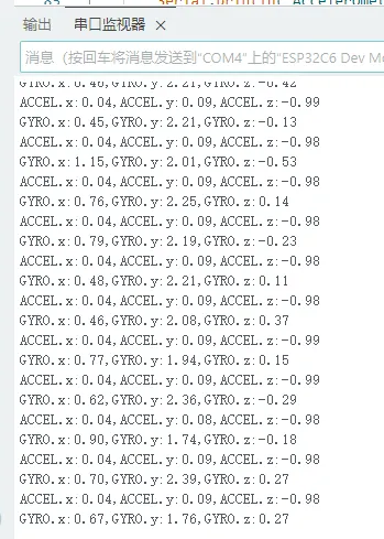
04_qmi8658_example
本示例打印了imu qmi8658的运行结果
代码
04_qmi8658_example.ino
#include <Arduino.h>
#include <Wire.h>
#include <SPI.h>
#include "SensorQMI8658.hpp"


// #define USE_I2C              //Using the I2C interface

#ifndef SENSOR_SDA
#define SENSOR_SDA  7
#endif

#ifndef SENSOR_SCL
#define SENSOR_SCL  8
#endif


#ifndef IMU_IRQ
#define IMU_IRQ  10
#endif


SensorQMI8658 qmi;

IMUdata acc;
IMUdata gyr;


void setup()
{
    Serial.begin(115200);
    while (!Serial);

    bool ret = false;

    ret = qmi.begin(Wire, QMI8658_L_SLAVE_ADDRESS, SENSOR_SDA, SENSOR_SCL);

    if (!ret) {
        Serial.println("Failed to find QMI8658 - check your wiring!");
        while (1) {
            delay(1000);
        }
    }

    /* Get chip id*/
    Serial.print("Device ID:");
    Serial.println(qmi.getChipID(), HEX);


    if (qmi.selfTestAccel()) {
        Serial.println("Accelerometer self-test successful");
    } else {
        Serial.println("Accelerometer self-test failed!");
    }

    if (qmi.selfTestGyro()) {
        Serial.println("Gyroscope self-test successful");
    } else {
        Serial.println("Gyroscope self-test failed!");
    }


    qmi.configAccelerometer(
        /*
         * ACC_RANGE_2G
         * ACC_RANGE_4G
         * ACC_RANGE_8G
         * ACC_RANGE_16G
         * */
        SensorQMI8658::ACC_RANGE_4G,
        /*
         * ACC_ODR_1000H
         * ACC_ODR_500Hz
         * ACC_ODR_250Hz
         * ACC_ODR_125Hz
         * ACC_ODR_62_5Hz
         * ACC_ODR_31_25Hz
         * ACC_ODR_LOWPOWER_128Hz
         * ACC_ODR_LOWPOWER_21Hz
         * ACC_ODR_LOWPOWER_11Hz
         * ACC_ODR_LOWPOWER_3H
        * */
        SensorQMI8658::ACC_ODR_1000Hz,
        /*
        *  LPF_MODE_0     //2.66% of ODR
        *  LPF_MODE_1     //3.63% of ODR
        *  LPF_MODE_2     //5.39% of ODR
        *  LPF_MODE_3     //13.37% of ODR
        *  LPF_OFF        // OFF Low-Pass Fitter
        * */
        SensorQMI8658::LPF_MODE_0);


    qmi.configGyroscope(
        /*
        * GYR_RANGE_16DPS
        * GYR_RANGE_32DPS
        * GYR_RANGE_64DPS
        * GYR_RANGE_128DPS
        * GYR_RANGE_256DPS
        * GYR_RANGE_512DPS
        * GYR_RANGE_1024DPS
        * */
        SensorQMI8658::GYR_RANGE_64DPS,
        /*
         * GYR_ODR_7174_4Hz
         * GYR_ODR_3587_2Hz
         * GYR_ODR_1793_6Hz
         * GYR_ODR_896_8Hz
         * GYR_ODR_448_4Hz
         * GYR_ODR_224_2Hz
         * GYR_ODR_112_1Hz
         * GYR_ODR_56_05Hz
         * GYR_ODR_28_025H
         * */
        SensorQMI8658::GYR_ODR_896_8Hz,
        /*
        *  LPF_MODE_0     //2.66% of ODR
        *  LPF_MODE_1     //3.63% of ODR
        *  LPF_MODE_2     //5.39% of ODR
        *  LPF_MODE_3     //13.37% of ODR
        *  LPF_OFF        // OFF Low-Pass Fitter
        * */
        SensorQMI8658::LPF_MODE_3);


    /*
    * If both the accelerometer and gyroscope sensors are turned on at the same time,
    * the output frequency will be based on the gyroscope output frequency.
    * The example configuration is 896.8HZ output frequency,
    * so the acceleration output frequency is also limited to 896.8HZ
    * */
    qmi.enableGyroscope();
    qmi.enableAccelerometer();

    // Print register configuration information
    qmi.dumpCtrlRegister();


#if IMU_IRQ > 0
// If you want to enable interrupts, then turn on the interrupt enable
    qmi.enableINT(SensorQMI8658::INTERRUPT_PIN_1, true);
    qmi.enableINT(SensorQMI8658::INTERRUPT_PIN_2, false);
#endif

    Serial.println("Read data now...");

}


void loop()
{
    // When the interrupt pin is passed in through setPin,
    // the GPIO will be read to see if the data is ready.
    if (qmi.getDataReady()) {

        // Serial.print("Timestamp:");
        // Serial.print(qmi.getTimestamp());

        if (qmi.getAccelerometer(acc.x, acc.y, acc.z)) {

            // Print to serial plotter
            Serial.print("ACCEL.x:"); Serial.print(acc.x); Serial.print(",");
            Serial.print("ACCEL.y:"); Serial.print(acc.y); Serial.print(",");
            Serial.print("ACCEL.z:"); Serial.print(acc.z); Serial.println();

            /*
            m2/s to mg
            Serial.print(" ACCEL.x:"); Serial.print(acc.x * 1000); Serial.println(" mg");
            Serial.print(",ACCEL.y:"); Serial.print(acc.y * 1000); Serial.println(" mg");
            Serial.print(",ACCEL.z:"); Serial.print(acc.z * 1000); Serial.println(" mg");
            */

        }

        if (qmi.getGyroscope(gyr.x, gyr.y, gyr.z)) {


            // Print to serial plotter
            Serial.print("GYRO.x:"); Serial.print(gyr.x); Serial.print(",");
            Serial.print("GYRO.y:"); Serial.print(gyr.y); Serial.print(",");
            Serial.print("GYRO.z:"); Serial.print(gyr.z); Serial.println();


            // Serial.print(" GYRO.x:"); Serial.print(gyr.x); Serial.println(" degrees/sec");
            // Serial.print(",GYRO.y:"); Serial.print(gyr.y); Serial.println(" degrees/sec");
            // Serial.print(",GYRO.z:"); Serial.print(gyr.z); Serial.println(" degrees/sec");

        }

        // Serial.print("Temperature:");
        // Serial.print(qmi.getTemperature_C());
        // Serial.println(" degrees C");

    }
    delay(100);
}
代码解释
-
初始化qmi8658 :
ret = qmi.begin(Wire, QMI8658_L_SLAVE_ADDRESS, SENSOR_SDA, SENSOR_SCL);
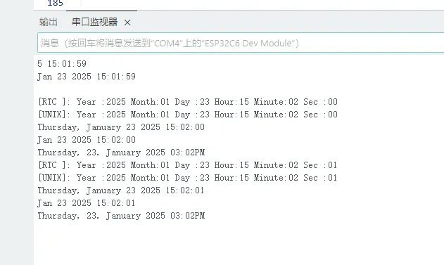
05_pcf85063_example
本示例打印出RTC实时时钟pcf85063的值
代码
05_pcf85063_example.ino
#include <Wire.h>
#include <SPI.h>
#include <Arduino.h>
#include <SensorPCF85063.hpp>

#ifndef SENSOR_SDA
#define SENSOR_SDA  7
#endif

#ifndef SENSOR_SCL
#define SENSOR_SCL  8
#endif

#ifndef SENSOR_IRQ
#define SENSOR_IRQ  15
#endif

SensorPCF85063 rtc;
uint32_t interval = 0;
uint32_t loopCount = 0;

void printInt(int val)
{
    if (val < 10) {
        Serial.print("0");
    }
    Serial.print(val);
}


void setup()
{

    Serial.begin(115200);
    // Wait for the serial port to be ready
    while (!Serial);

    // Try to initialize the RTC module using I2C with specified SDA and SCL pins
    if (!rtc.begin(Wire, SENSOR_SDA, SENSOR_SCL)) {
        Serial.println("Failed to find PCF85063 - check your wiring!");
        // Enter an infinite loop to halt the program
        while (1) {
            delay(1000);
        }
    }

    uint16_t year = 2023;
    uint8_t month = 9;
    uint8_t day = 7;
    uint8_t hour = 11;
    uint8_t minute = 24;
    uint8_t second = 30;

    // Set the defined date and time on the RTC
    rtc.setDateTime(year, month, day, hour, minute, second);

    if (!rtc.isClockIntegrityGuaranteed()) {
        Serial.println("[ERROR]:Clock integrity is not guaranteed; oscillator has stopped or has been interrupted");
    }
}

void loop()
{
    // Check if one second has passed since the last update
    if (millis() > interval) {

        // Update the interval to the current time
        interval = millis() + 1000;

        // Retrieve the current date and time from the RTC
        RTC_DateTime datetime = rtc.getDateTime();

        Serial.print("[RTC ]:");
        Serial.print(" Year :");  printInt(datetime.getYear());
        Serial.print(" Month:");  printInt(datetime.getMonth());
        Serial.print(" Day :");   printInt(datetime.getDay());
        Serial.print(" Hour:");   printInt(datetime.getHour());
        Serial.print(" Minute:"); printInt(datetime.getMinute());
        Serial.print(" Sec :");   printInt(datetime.getSecond());
        Serial.println();

        // Convert the RTC date and time to Unix time
        struct tm info = datetime.toUnixTime();
        Serial.print("[UNIX]:");
        Serial.print(" Year :");  printInt(info.tm_year + 1900); // tm_year starts counting from 1900
        Serial.print(" Month:");  printInt(info.tm_mon + 1);     // tm_mon range is 0 - 11, 0 means January
        Serial.print(" Day :");   printInt(info.tm_mday);
        Serial.print(" Hour:");   printInt(info.tm_hour);
        Serial.print(" Minute:"); printInt(info.tm_min);
        Serial.print(" Sec :");   printInt(info.tm_sec);
        Serial.println();

        // Set a new Unix time at the 10th loop iteration
        if (loopCount == 10) {
            Serial.print("Set Unix Time:");
            Serial.println();
            Serial.println();
            struct tm utc_tm;
            utc_tm.tm_year = 2025 - 1900; // tm_year starts counting from 1900
            utc_tm.tm_mon = 0;            // tm_mon range is 0 - 11, 0 means January
            utc_tm.tm_mday = 23;
            utc_tm.tm_hour = 7;
            utc_tm.tm_min = 1;
            utc_tm.tm_sec = 28;
            rtc.setDateTime(utc_tm);
        }

        // Set a UTC time with a time zone offset of 8 hours at the 20th loop iteration
        if (loopCount == 20) {
            Serial.print("Set UTC time to time zone offset 8 hours:");
            Serial.println();
            Serial.println();
            struct tm utc_tm;
            utc_tm.tm_year = 2025 - 1900; // tm_year starts counting from 1900
            utc_tm.tm_mon = 0;            // tm_mon range is 0 - 11, 0 means January
            utc_tm.tm_mday = 23;
            utc_tm.tm_hour = 7;
            utc_tm.tm_min = 1;
            utc_tm.tm_sec = 28;
            rtc.convertUtcToTimezone(utc_tm, 8 * 3600);
            rtc.setDateTime(utc_tm);
        }

        if (loopCount > 30) {

            char buf[64];

            struct tm timeinfo;
            // Get the time C library structure
            rtc.getDateTime(&timeinfo);

            // Format the output using the strftime function
            // For more formats, please refer to :
            // https://man7.org/linux/man-pages/man3/strftime.3.html

            size_t written = strftime(buf, 64, "%A, %B %d %Y %H:%M:%S", &timeinfo);

            if (written != 0) {
                Serial.println(buf);
            }

            written = strftime(buf, 64, "%b %d %Y %H:%M:%S", &timeinfo);
            if (written != 0) {
                Serial.println(buf);
            }

            written = strftime(buf, 64, "%A, %d. %B %Y %I:%M%p", &timeinfo);
            if (written != 0) {
                Serial.println(buf);
            }
        }

        ++loopCount;
    }
}
代码解释
-
初始化PCF85063 :
if (!rtc.begin(Wire, SENSOR_SDA, SENSOR_SCL)) {Serial.println("Failed to find PCF85063 - check your wiring!");// Enter an infinite loop to halt the programwhile (1) {delay(1000);}} -
设置时间 :
uint16_t year = 2023;uint8_t month = 9;uint8_t day = 7;uint8_t hour = 11;uint8_t minute = 24;uint8_t second = 30;// Set the defined date and time on the RTCrtc.setDateTime(year, month, day, hour, minute, second);
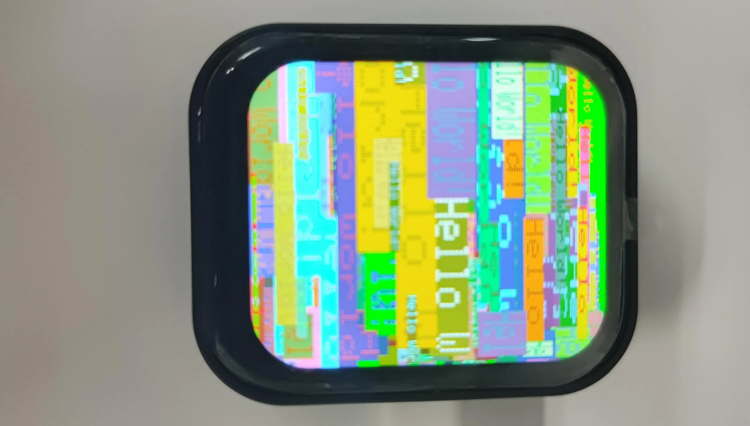
06_gfx_helloworld
本示例驱动屏幕,并在屏幕上不断打印helloworld。
代码
06_gfx_helloworld.ino
#include <Arduino_GFX_Library.h>

#define LCD_SCK 1
#define LCD_DIN 2
#define LCD_CS 5
#define LCD_DC 3
#define LCD_RST 4
#define LCD_BL 6

#define GFX_BL LCD_BL

Arduino_DataBus *bus = new Arduino_HWSPI(LCD_DC, LCD_CS, LCD_SCK, LCD_DIN);
Arduino_GFX *gfx = new Arduino_ST7789(
  bus, LCD_RST, 0 /* rotation */, true /* IPS */,
  240 /* width */, 284 /* height */);

void setup(void)
{
#ifdef DEV_DEVICE_INIT
  DEV_DEVICE_INIT();
#endif

  Serial.begin(115200);
  // Serial.setDebugOutput(true);
  // while(!Serial);
  Serial.println("Arduino_GFX Hello World example");

  // Init Display
  if (!gfx->begin())
  {
    Serial.println("gfx->begin() failed!");
  }
  gfx->fillScreen(RGB565_BLACK);

#ifdef GFX_BL
  pinMode(GFX_BL, OUTPUT);
  digitalWrite(GFX_BL, HIGH);
#endif

  while(1) {
    gfx->fillScreen(RGB565_BLUE);
    delay(1000);
    gfx->fillScreen(RGB565_RED);
    delay(1000);
    gfx->fillScreen(RGB565_GREEN);
    delay(1000);
  }

  gfx->setCursor(10, 10);
  gfx->setTextColor(RGB565_RED);
  gfx->println("Hello World!");

  delay(5000); // 5 seconds
}

void loop()
{
  gfx->setCursor(random(gfx->width()), random(gfx->height()));
  gfx->setTextColor(random(0xffff), random(0xffff));
  gfx->setTextSize(random(6) /* x scale */, random(6) /* y scale */, random(2) /* pixel_margin */);
  gfx->println("Hello World!");

  delay(1000); // 1 second
}
代码解释
-
初始化SPI总线以及屏幕 :
Arduino_DataBus *bus = new Arduino_HWSPI(LCD_DC, LCD_CS, LCD_SCK, LCD_DIN);Arduino_GFX *gfx = new Arduino_ST7789(bus, LCD_RST, 0 /* rotation */, true /* IPS */,240 /* width */, 284 /* height */); -
填充Hello World :
gfx->setCursor(random(gfx->width()), random(gfx->height()));gfx->setTextColor(random(0xffff), random(0xffff));gfx->setTextSize(random(6) /* x scale */, random(6) /* y scale */, random(2) /* pixel_margin */);gfx->println("Hello World!");
07_LVGL_Arduino
本示例使用Arduino_GFX_Library驱动ST7789屏幕,同时移植LVGL,以及触摸驱动

代码
07_LVGL_Arduino.ino
#include <lvgl.h>
#include <Arduino_GFX_Library.h>
#include "Arduino_DriveBus_Library.h"
#include "lv_conf.h"
#include <demos/lv_demos.h>
#include "HWCDC.h"


HWCDC USBSerial;

#define LCD_SCK 1
#define LCD_DIN 2
#define LCD_CS 5
#define LCD_DC 3
#define LCD_RST 4
#define LCD_BL 6

#define GFX_BL LCD_BL

#define LCD_WIDTH 240
#define LCD_HEIGHT 284

#define IIC_SDA 7
#define IIC_SCL 8

#define TP_INT 11

Arduino_DataBus *bus = new Arduino_HWSPI(LCD_DC, LCD_CS, LCD_SCK, LCD_DIN);
Arduino_GFX *gfx = new Arduino_ST7789(
  bus, LCD_RST, 0 /* rotation */, true /* IPS */,
  LCD_WIDTH /* width */, LCD_HEIGHT /* height */);

std::shared_ptr<Arduino_IIC_DriveBus> IIC_Bus =
  std::make_shared<Arduino_HWIIC>(IIC_SDA, IIC_SCL, &Wire);

void Arduino_IIC_Touch_Interrupt(void);

std::unique_ptr<Arduino_IIC> CST816T(new Arduino_CST816x(IIC_Bus, CST816T_DEVICE_ADDRESS,
                                                         -1, TP_INT, Arduino_IIC_Touch_Interrupt));

void Arduino_IIC_Touch_Interrupt(void) {
  CST816T->IIC_Interrupt_Flag = true;
}

#define EXAMPLE_LVGL_TICK_PERIOD_MS 2

uint32_t screenWidth;
uint32_t screenHeight;

static lv_disp_draw_buf_t draw_buf;
// static lv_color_t buf[screenWidth * screenHeight / 10];


#if LV_USE_LOG != 0
/* Serial debugging */
void my_print(const char *buf) {
  Serial.printf(buf);
  Serial.flush();
}
#endif

/* Display flushing */
void my_disp_flush(lv_disp_drv_t *disp, const lv_area_t *area, lv_color_t *color_p) {
  uint32_t w = (area->x2 - area->x1 + 1);
  uint32_t h = (area->y2 - area->y1 + 1);

#if (LV_COLOR_16_SWAP != 0)
  gfx->draw16bitBeRGBBitmap(area->x1, area->y1, (uint16_t *)&color_p->full, w, h);
#else
  gfx->draw16bitRGBBitmap(area->x1, area->y1, (uint16_t *)&color_p->full, w, h);
#endif

  lv_disp_flush_ready(disp);
}

void example_increase_lvgl_tick(void *arg) {
  /* Tell LVGL how many milliseconds has elapsed */
  lv_tick_inc(EXAMPLE_LVGL_TICK_PERIOD_MS);
}

static uint8_t count = 0;
void example_increase_reboot(void *arg) {
  count++;
  if (count == 30) {
    esp_restart();
  }
}

/*Read the touchpad*/
void my_touchpad_read(lv_indev_drv_t *indev_driver, lv_indev_data_t *data) {
  int32_t touchX = CST816T->IIC_Read_Device_Value(CST816T->Arduino_IIC_Touch::Value_Information::TOUCH_COORDINATE_X);
  int32_t touchY = CST816T->IIC_Read_Device_Value(CST816T->Arduino_IIC_Touch::Value_Information::TOUCH_COORDINATE_Y);

  if (CST816T->IIC_Interrupt_Flag == true) {
    CST816T->IIC_Interrupt_Flag = false;
    data->state = LV_INDEV_STATE_PR;

    /* Set the coordinates with some debounce */
    if (touchX >= 0 && touchY >= 0) {
      data->point.x = touchX;
      data->point.y = touchY;

      USBSerial.printf("Data x: %d, Data y: %d\n", touchX, touchY);
    }
  } else {
    data->state = LV_INDEV_STATE_REL;
  }
}


void setup() {
  USBSerial.begin(115200); /* prepare for possible serial debug */

  while (CST816T->begin() == false) {
    USBSerial.println("CST816T initialization fail");
    delay(2000);
  }
  USBSerial.println("CST816T initialization successfully");

  CST816T->IIC_Write_Device_State(CST816T->Arduino_IIC_Touch::Device::TOUCH_DEVICE_INTERRUPT_MODE,
                                  CST816T->Arduino_IIC_Touch::Device_Mode::TOUCH_DEVICE_INTERRUPT_PERIODIC);

  gfx->begin();
  pinMode(LCD_BL, OUTPUT);
  digitalWrite(LCD_BL, HIGH);

  screenWidth = gfx->width();
  screenHeight = gfx->height();

  lv_init();

  lv_color_t *buf1 = (lv_color_t *)heap_caps_malloc(screenWidth * screenHeight / 4 * sizeof(lv_color_t), MALLOC_CAP_DMA);

  lv_color_t *buf2 = (lv_color_t *)heap_caps_malloc(screenWidth * screenHeight / 4 * sizeof(lv_color_t), MALLOC_CAP_DMA);

  String LVGL_Arduino = "Hello Arduino! ";
  LVGL_Arduino += String('V') + lv_version_major() + "." + lv_version_minor() + "." + lv_version_patch();

  USBSerial.println(LVGL_Arduino);
  USBSerial.println("I am LVGL_Arduino");


#if LV_USE_LOG != 0
  lv_log_register_print_cb(my_print); /* register print function for debugging */
#endif

  lv_disp_draw_buf_init(&draw_buf, buf1, buf2, screenWidth * screenHeight / 4);

  /*Initialize the display*/
  static lv_disp_drv_t disp_drv;
  lv_disp_drv_init(&disp_drv);
  /*Change the following line to your display resolution*/
  disp_drv.hor_res = screenWidth;
  disp_drv.ver_res = screenHeight;
  disp_drv.flush_cb = my_disp_flush;
  disp_drv.draw_buf = &draw_buf;
  lv_disp_drv_register(&disp_drv);

  /*Initialize the (dummy) input device driver*/
  static lv_indev_drv_t indev_drv;
  lv_indev_drv_init(&indev_drv);
  indev_drv.type = LV_INDEV_TYPE_POINTER;
  indev_drv.read_cb = my_touchpad_read;
  lv_indev_drv_register(&indev_drv);

  lv_obj_t *label = lv_label_create(lv_scr_act());
  lv_label_set_text(label, "Hello Ardino and LVGL!");
  lv_obj_align(label, LV_ALIGN_CENTER, 0, 0);

  const esp_timer_create_args_t lvgl_tick_timer_args = {
    .callback = &example_increase_lvgl_tick,
    .name = "lvgl_tick"
  };

  const esp_timer_create_args_t reboot_timer_args = {
    .callback = &example_increase_reboot,
    .name = "reboot"
  };

  esp_timer_handle_t lvgl_tick_timer = NULL;
  esp_timer_create(&lvgl_tick_timer_args, &lvgl_tick_timer);
  esp_timer_start_periodic(lvgl_tick_timer, EXAMPLE_LVGL_TICK_PERIOD_MS * 1000);

  lv_demo_widgets();
  // lv_demo_benchmark();
  // lv_demo_keypad_encoder();
  // lv_demo_music();
  // lv_demo_stress();

  // lv_obj_t *img_obj = lv_img_create(lv_scr_act());
  // lv_img_set_src(img_obj, &img_test3);  // Set the image source to img_test3
  // lv_obj_align(img_obj, LV_ALIGN_CENTER, 0, 0);
  // USBSerial.println("Setup done");
}

void loop() {
  lv_timer_handler(); /* let the GUI do its work */
  delay(5);
}
代码解释
-
初始化SPI总线以及屏幕 :
Arduino_DataBus *bus = new Arduino_HWSPI(LCD_DC, LCD_CS, LCD_SCK, LCD_DIN);Arduino_GFX *gfx = new Arduino_ST7789(bus, LCD_RST, 0 /* rotation */, true /* IPS */,LCD_WIDTH /* width */, LCD_HEIGHT /* height */); -
初始化触摸芯片CST816 :
std::unique_ptr<Arduino_IIC> CST816T(new Arduino_CST816x(IIC_Bus, CST816T_DEVICE_ADDRESS,-1, TP_INT, Arduino_IIC_Touch_Interrupt)); -
初始化LVGL,配置触摸驱动,并显示加载LVGL示例程序 :
screenWidth = gfx->width();screenHeight = gfx->height();lv_init();lv_color_t *buf1 = (lv_color_t *)heap_caps_malloc(screenWidth * screenHeight / 4 * sizeof(lv_color_t), MALLOC_CAP_DMA);lv_color_t *buf2 = (lv_color_t *)heap_caps_malloc(screenWidth * screenHeight / 4 * sizeof(lv_color_t), MALLOC_CAP_DMA);String LVGL_Arduino = "Hello Arduino! ";LVGL_Arduino += String('V') + lv_version_major() + "." + lv_version_minor() + "." + lv_version_patch();USBSerial.println(LVGL_Arduino);USBSerial.println("I am LVGL_Arduino");#if LV_USE_LOG != 0lv_log_register_print_cb(my_print); /* register print function for debugging */#endiflv_disp_draw_buf_init(&draw_buf, buf1, buf2, screenWidth * screenHeight / 4);/*Initialize the display*/static lv_disp_drv_t disp_drv;lv_disp_drv_init(&disp_drv);/*Change the following line to your display resolution*/disp_drv.hor_res = screenWidth;disp_drv.ver_res = screenHeight;disp_drv.flush_cb = my_disp_flush;disp_drv.draw_buf = &draw_buf;lv_disp_drv_register(&disp_drv);/*Initialize the (dummy) input device driver*/static lv_indev_drv_t indev_drv;lv_indev_drv_init(&indev_drv);indev_drv.type = LV_INDEV_TYPE_POINTER;indev_drv.read_cb = my_touchpad_read;lv_indev_drv_register(&indev_drv);lv_obj_t *label = lv_label_create(lv_scr_act());lv_label_set_text(label, "Hello Ardino and LVGL!");lv_obj_align(label, LV_ALIGN_CENTER, 0, 0);const esp_timer_create_args_t lvgl_tick_timer_args = {.callback = &example_increase_lvgl_tick,.name = "lvgl_tick"};const esp_timer_create_args_t reboot_timer_args = {.callback = &example_increase_reboot,.name = "reboot"};esp_timer_handle_t lvgl_tick_timer = NULL;esp_timer_create(&lvgl_tick_timer_args, &lvgl_tick_timer);esp_timer_start_periodic(lvgl_tick_timer, EXAMPLE_LVGL_TICK_PERIOD_MS * 1000);lv_demo_widgets();