Arduino 开发
本章节包含以下部分,请按需阅读:
Arduino 入门教程
初次接触 Arduino ESP32 开发,想要快速上手?我们为您准备了一套通用的 入门教程。
- 第0节 认识 ESP32
- 第1节 安装和配置 Arduino IDE
- 第2节 Arduino 基础知识
- 第3节 数字输出/输入
- 第4节 模拟输入
- 第5节 脉冲宽度调制 (PWM)
- 第6节 串行通信 (UART)
- 第7节 I2C 通信
- 第8节 SPI 通信
- 第9节 Wi-Fi 基础用法
- 第10节 网页服务器
- 第11节 蓝牙 (Bluetooth)
- 第12节 LVGL 图形界面开发
- 第13节 综合项目
请注意:该教程使用 ESP32-S3-Zero 作为教学示例,所有硬件代码均基于其引脚布局。在动手实践前,建议您对照手中的开发板引脚图,确认引脚配置无误。
配置开发环境
1. 安装和配置 Arduino IDE
请参考 安装和配置 Arduino IDE 教程 下载安装 Arduino IDE 并添加 ESP32 支持。
| 板名称 | 板安装要求 | 版本号要求 |
|---|---|---|
| esp32 by Espressif Systems | “离线”安装/“在线”安装 | 3.0.5 |
2. 安装库
要运行示例,需要安装对应的库。示例代码使用 GFX Library for Arduino 库驱动 ST7789V2 显示屏
,并使用 Arduino_DriveBus 库驱动 CST816T 触摸芯片。
可从 此链接 下载 ESP32-S3-Touch-LCD-1.69 开发板的示例程序包。包内的 Arduino\libraries 目录已包含本教程所需的全部库文件。
| 库或文件名称 | 说明 | 版本 | 安装方式 |
|---|---|---|---|
| Arduino_DriveBus | CST816 触摸芯片驱动库 | v1.0.1 | 手动安装 |
| GFX Library for Arduino | ST7789 显示驱动图形库 | v1.6.5 | 通过库管理器或手动安装 |
| SensorLib | PCF85063、QMI8658 传感器驱动库 | v0.4.1 | 通过库管理器或手动安装 |
| lvgl | LVGL 图形库 | v8.4.0 | 通过库管理器或手动安装 |
| Mylibrary/pin_config.h | 开发板引脚宏定义,兼容板卡宏定义 | —— | 手动安装 |
| lv_conf.h | LVGL 配置文件,性能监视器居中显示 | —— | 手动安装 |
LVGL 及其驱动库的版本之间存在较强的依赖关系。例如,为 LVGL v8 编写的驱动可能不兼容 LVGL v9。为确保示例能够稳定复现,推荐使用上表列出的特定版本。混合使用不同版本的库可能导致编译失败或运行时异常。
安装步骤:
-
解压已下载的 示例程序包。
-
将其
Arduino\libraries目录下的所有文件夹(Arduino_DriveBus、GFX_Library_for_Arduino 等)复制到 Arduino 的库文件夹中。信息Arduino 库文件夹的路径通常是:
c:\Users\<用户名>\Documents\Arduino\libraries。也可以在 Arduino IDE 中通过 文件 > 首选项,查看“项目文件夹位置”来定位。库文件夹就是此路径下的
libraries文件夹。 -
其他安装方式请参考:Arduino 库管理教程。
3. 其他提示
-
ESP32-S3-Touch-LCD-1.69 支持在 Arduino IDE 中直接选择型号。
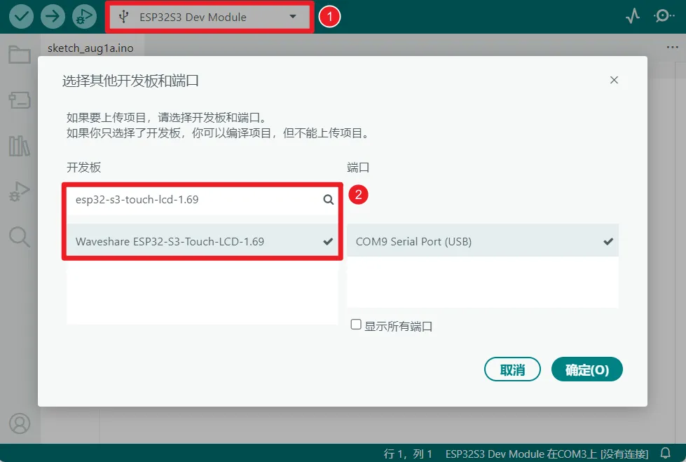
-
ESP32-S3-Touch-LCD-1.69 使用 ESP32-S3 原生 USB 接口,而非 UART 转 USB。对于串口通信:
-
printf()函数可直接使用; -
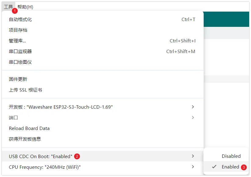
若要使用
Serial.println()函数,需要额外配置:在 IDE 工具菜单中启用"USB CDC On Boot"选项,或在代码中声明 HWCDC 对象处理 USB 串口通信。备注如下图所示,在 Arduino IDE 的"工具"选项中设置"USB CDC On Boot"
-
示例程序
Arduino 示例程序位于 示例程序包 的 Arduino/examples 目录中。
| 示例程序 | 基础例程说明 | 依赖库 |
|---|---|---|
| 01_HelloWorld | 展示基本的图形库功能,也可以用于测试显示屏的基础性能以及随机文本显示效果 | GFX_Library_for_Arduino |
| 02_Drawing_board | 读取 CST816T 触摸坐标,并在屏幕上绘制连续触摸轨迹 | GFX_Library_for_Arduino,Arduino DriveBus |
| 03_GFX_AsciiTable | 根据屏幕尺寸,在显示屏上按行列打印 ASCII 字符 | GFX_Library_for_Arduino |
| 04_GFX_ESPWiFiAnalyzer | 在 ST7789 显示器上绘制 WiFi 频段信号强度 | GFX_Library_for_Arduino |
| 05_GFX_Clock | 一个简单的 ST7789 时钟示例,通过简单的标记指针和时间管理实现时钟 | GFX_Library_for_Arduino |
| 06_GFX_PCF85063_simpleTime | 居中显示当前日期和时间 | SensorLib,GFX_Library_for_Arduino |
| 07_LVGL_Measuring_voltage | 板上预留分压测电压,使用 GPIO1 读取模拟量值并通过分压公式得出电池电压 | LVGL |
| 08_LVGL_PCF85063_simpleTime | 在 LVGL 下使用 PCF85063 RTC 模块在 ST7789 显示屏上显示当前时间 | LVGL,SensorLib |
| 09_LVGL_Keys_Bee | 多功能按钮使用 | LVGL |
| 10_LVGL_QMI8658_ui | 使用 LVGL 曲线图实时显示 QMI8658 加速度计和陀螺仪三轴数据变化 | LVGL,SensorLib |
| 11_LVGL_Arduino | LVGL 演示 | LVGL,Arduino DriveBus |
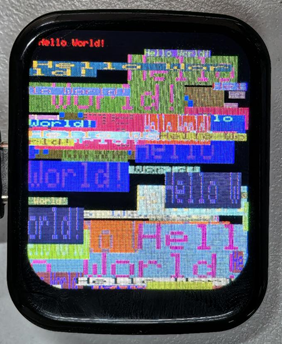
01_HelloWorld
本示例展示如何使用 ST7789 显示屏,结合 Arduino GFX 库和 Arduino DriveBus 库实现动态文本显示。具体来说,它在显示屏上固定位置显示文本“Hello World!”后,在循环中每隔一秒随机选择新的位置、颜色和大小再次显示这段文本。该代码也可以用于测试显示屏的基础性能。
代码
01_HelloWorld.ino
#include <Arduino.h>
#include "Arduino_GFX_Library.h"
#include "pin_config.h"
#include <Wire.h>
#include "HWCDC.h"

HWCDC USBSerial;

Arduino_DataBus *bus = new Arduino_ESP32SPI(LCD_DC, LCD_CS, LCD_SCK, LCD_MOSI);

Arduino_GFX *gfx = new Arduino_ST7789(bus, LCD_RST /* RST */,
                                      0 /* rotation */, true /* IPS */, LCD_WIDTH, LCD_HEIGHT, 0, 20, 0, 0);

void setup(void) {
  USBSerial.begin(115200);
  // USBSerial.setDebugOutput(true);
  // while(!USBSerial);
  USBSerial.println("Arduino_GFX Hello World example");

  // Init Display
  if (!gfx->begin()) {
    USBSerial.println("gfx->begin() failed!");
  }
  gfx->fillScreen(RGB565_BLACK);

  pinMode(LCD_BL, OUTPUT);
  digitalWrite(LCD_BL, HIGH);

  gfx->setCursor(10, 10);
  gfx->setTextColor(RGB565_RED);
  gfx->println("Hello World!");

  delay(5000);  // 5 seconds
}

void loop() {
  gfx->setCursor(random(gfx->width()), random(gfx->height()));
  gfx->setTextColor(random(0xffff), random(0xffff));
  gfx->setTextSize(random(6) /* x scale */, random(6) /* y scale */, random(2) /* pixel_margin */);
  gfx->println("Hello World!");

  delay(1000);  // 1 second
}
代码解释
-
显示初始化 :
if (!gfx->begin()) {USBSerial.println("gfx->begin() failed!");} -
清屏并显示文本 :
gfx->fillScreen(RGB565_BLACK);gfx->setCursor(10, 10);gfx->setTextColor(RGB565_RED);gfx->println("Hello World!"); -
动图显示 :
gfx->setCursor(random(gfx->width()), random(gfx->height()));gfx->setTextColor(random(0xffff), random(0xffff));gfx->setTextSize(random(6), random(6), random(2));gfx->println("Hello World!");
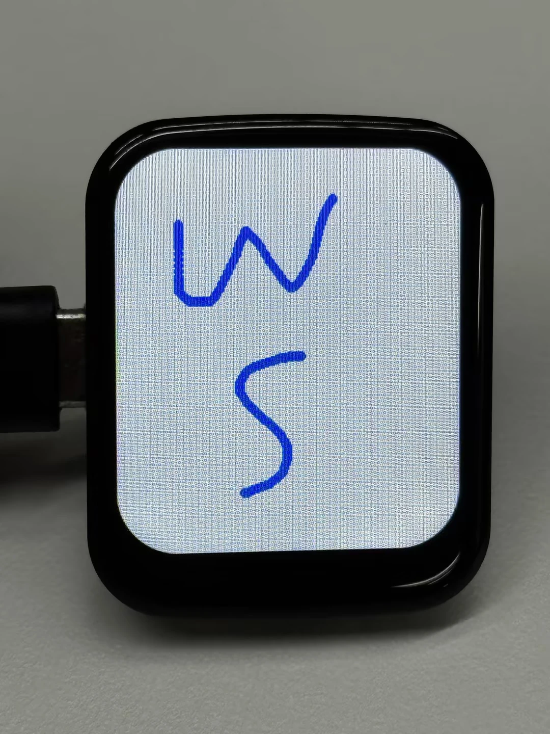
02_Drawing_board
本示例演示如何使用 CST816T 触摸 IC 和 Arduino GFX 库在 ESP32 开发板上实现触摸绘图。代码将触摸、显示初始化拆分为独立函数,使用 400 kHz I2C 速度读取触摸中断和坐标,并在连续触摸时连接相邻触点形成更平滑的轨迹。程序启动时,它还通过 PWM 调节背光展示从暗到亮的加载效果。
代码
02_Drawing_board.ino
#include <Wire.h>
#include <Arduino.h>
#include "pin_config.h"
#include "Arduino_GFX_Library.h"
#include "Arduino_DriveBus_Library.h"
#include "HWCDC.h"
HWCDC USBSerial;
Arduino_DataBus *bus = new Arduino_ESP32SPI(LCD_DC, LCD_CS, LCD_SCK, LCD_MOSI);
Arduino_GFX *gfx = new Arduino_ST7789(bus, LCD_RST /* RST */,
0 /* rotation */, true /* IPS */, LCD_WIDTH, LCD_HEIGHT, 0, 20, 0, 0);
static constexpr uint16_t DRAW_COLOR = RGB565_BLUE;
static constexpr uint16_t BACKGROUND_COLOR = RGB565_WHITE;
static constexpr int16_t DRAW_RADIUS = 3;
static constexpr int16_t LOADING_TEXT_X = 20;
static constexpr int16_t LOADING_TEXT_Y = 100;
static constexpr uint32_t TOUCH_STROKE_TIMEOUT_MS = 150;
static constexpr uint32_t TOUCH_LOG_INTERVAL_MS = 100;
static constexpr uint32_t TOUCH_I2C_SPEED = 400000;
std::shared_ptr<Arduino_IIC_DriveBus> IIC_Bus =
std::make_shared<Arduino_HWIIC>(IIC_SDA, IIC_SCL, &Wire);
void Arduino_IIC_Touch_Interrupt(void);
std::unique_ptr<Arduino_IIC> CST816T(new Arduino_CST816x(IIC_Bus, CST816T_DEVICE_ADDRESS,
TP_RST, TP_INT, Arduino_IIC_Touch_Interrupt));
struct TouchState {
int16_t lastX = -1;
int16_t lastY = -1;
uint32_t lastTouchMs = 0;
uint32_t lastLogMs = 0;
};
TouchState touchState;
void Arduino_IIC_Touch_Interrupt(void) {
CST816T->IIC_Interrupt_Flag = true;
}
void initializeTouch() {
while (CST816T->begin(TOUCH_I2C_SPEED) == false) {
USBSerial.println("CST816T initialization fail");
delay(2000);
}
USBSerial.println("CST816T initialization successfully");
CST816T->IIC_Write_Device_State(CST816T->Arduino_IIC_Touch::Device::TOUCH_DEVICE_INTERRUPT_MODE,
CST816T->Arduino_IIC_Touch::Device_Mode::TOUCH_DEVICE_INTERRUPT_PERIODIC);
CST816T->IIC_Interrupt_Flag = false;
}
void showLoadingScreen() {
gfx->fillScreen(BACKGROUND_COLOR);
gfx->setCursor(LOADING_TEXT_X, LOADING_TEXT_Y);
gfx->setTextColor(DRAW_COLOR);
gfx->setTextSize(2);
for (int brightness = 0; brightness <= 255; brightness++) {
analogWrite(LCD_BL, brightness);
gfx->println("Loading board");
delay(3);
gfx->setCursor(LOADING_TEXT_X, LOADING_TEXT_Y);
}
delay(500);
gfx->fillScreen(BACKGROUND_COLOR);
}
void initializeDisplay() {
gfx->begin();
pinMode(LCD_BL, OUTPUT);
digitalWrite(LCD_BL, HIGH);
showLoadingScreen();
}
bool readTouchPoint(int16_t &touchX, int16_t &touchY) {
if (CST816T->IIC_Interrupt_Flag != true) {
return false;
}
CST816T->IIC_Interrupt_Flag = false;
int32_t fingers = CST816T->IIC_Read_Device_Value(CST816T->Arduino_IIC_Touch::Value_Information::TOUCH_FINGER_NUMBER);
if (fingers <= 0) {
touchState.lastX = -1;
touchState.lastY = -1;
return false;
}
int32_t rawX = CST816T->IIC_Read_Device_Value(CST816T->Arduino_IIC_Touch::Value_Information::TOUCH_COORDINATE_X);
int32_t rawY = CST816T->IIC_Read_Device_Value(CST816T->Arduino_IIC_Touch::Value_Information::TOUCH_COORDINATE_Y);
if (rawX < 0 || rawY < 0) {
return false;
}
touchX = constrain((int16_t)rawX, 0, LCD_WIDTH - 1);
touchY = constrain((int16_t)rawY, 0, LCD_HEIGHT - 1);
return true;
}
void drawTouchPoint(int16_t touchX, int16_t touchY) {
uint32_t now = millis();
// When two touch points are close in time, connect them so the stroke feels continuous.
if (touchState.lastX >= 0 && touchState.lastY >= 0 &&
(now - touchState.lastTouchMs) <= TOUCH_STROKE_TIMEOUT_MS) {
gfx->drawLine(touchState.lastX, touchState.lastY, touchX, touchY, DRAW_COLOR);
}
gfx->fillCircle(touchX, touchY, DRAW_RADIUS, DRAW_COLOR);
touchState.lastX = touchX;
touchState.lastY = touchY;
touchState.lastTouchMs = now;
if ((now - touchState.lastLogMs) >= TOUCH_LOG_INTERVAL_MS) {
USBSerial.printf("Touch X:%d Y:%d\n", touchX, touchY);
touchState.lastLogMs = now;
}
}
void setup() {
USBSerial.begin(115200);
initializeTouch();
initializeDisplay();
}
void loop() {
int16_t touchX = 0;
int16_t touchY = 0;
if (!readTouchPoint(touchX, touchY)) {
return;
}
drawTouchPoint(touchX, touchY);
}
代码解释
-
触摸与显示初始化 :
initializeTouch();initializeDisplay(); -
触摸绘制 :
readTouchPoint()只在触摸中断触发后读取坐标,并使用constrain()将坐标限制在屏幕范围内。drawTouchPoint()会在 150 ms 内的连续触摸点之间绘制连线,同时用圆点补齐笔触。
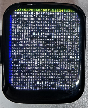
03_GFX_AsciiTable
本示例展示如何用 ST7789 显示屏结合 Arduino GFX 库,创建一个 ASCII 表格的显示效果。具体而言,代码初始化显示屏后,按照预定义的颜色和位置在屏幕上显示 ASCII 字符索引。首先,“Arduino_GFX AsciiTable example” 字样通过 USBSerial 打印到串口监视器,然后在屏幕上按照两种颜色(绿色和蓝色)固定显示索引,接着用白色在黑色背景上显示完整 ASCII 字符表。
代码
03_GFX_AsciiTable.ino
#include <Arduino.h>
#include "Arduino_GFX_Library.h"
#include "pin_config.h"
#include <Wire.h>
#include "HWCDC.h"
HWCDC USBSerial;
Arduino_DataBus *bus = new Arduino_ESP32SPI(LCD_DC, LCD_CS, LCD_SCK, LCD_MOSI);
Arduino_GFX *gfx = new Arduino_ST7789(bus, LCD_RST /* RST */,
0 /* rotation */, true /* IPS */, LCD_WIDTH, LCD_HEIGHT, 0, 20, 0, 0);
static constexpr uint16_t BACKGROUND_COLOR = RGB565_BLACK;
static constexpr uint16_t HEADER_TEXT_COLOR = RGB565_GREEN;
static constexpr uint16_t INDEX_TEXT_COLOR = RGB565_BLUE;
static constexpr uint16_t ASCII_TEXT_COLOR = RGB565_WHITE;
void setup(void) {
USBSerial.begin(115200);
// USBSerial.setDebugOutput(true);
// while(!USBSerial);
USBSerial.println("Arduino_GFX AsciiTable example");
int columnCount = LCD_WIDTH / 8;
int rowCount = LCD_HEIGHT / 10;
#ifdef GFX_EXTRA_PRE_INIT
GFX_EXTRA_PRE_INIT();
#endif
// Init Display
if (!gfx->begin()) {
   USBSerial.println("gfx->begin() failed!");
 }
gfx->fillScreen(BACKGROUND_COLOR);
pinMode(LCD_BL, OUTPUT);
digitalWrite(LCD_BL, HIGH);
gfx->setTextColor(HEADER_TEXT_COLOR);
for (int x = 0; x < columnCount; x++) {
gfx->setCursor(10 + x * 8, 2);
gfx->print(x, 16);
}
gfx->setTextColor(INDEX_TEXT_COLOR);
for (int y = 0; y < rowCount; y++) {
gfx->setCursor(2, 12 + y * 10);
gfx->print(y, 16);
}
char c = 0;
for (int y = 0; y < rowCount; y++) {
for (int x = 0; x < columnCount; x++) {
gfx->drawChar(10 + x * 8, 12 + y * 10, c++, ASCII_TEXT_COLOR, BACKGROUND_COLOR);
}
}
delay(5000); // 5 seconds
}
void loop() {
}
代码解释
-
初始化显示屏 :
if (!gfx->begin()) {USBSerial.println("gfx->begin() failed!");} -
计算行列并标注编号 :
这里根据显示屏的尺寸计算出可以显示的列数和行数。然后分别使用两个循环,设置不同的文本颜色,在显示屏上打印出行和列的编号,以便在后续绘制 ASCII 字符时可以方便地确定字符的位置。
int columnCount = LCD_WIDTH / 8;int rowCount = LCD_HEIGHT / 10;// 标注列编号gfx->setTextColor(HEADER_TEXT_COLOR);for (int x = 0; x < columnCount; x++) {gfx->setCursor(10 + x * 8, 2);gfx->print(x, 16);}// 标注行编号gfx->setTextColor(INDEX_TEXT_COLOR);for (int y = 0; y < rowCount; y++) {gfx->setCursor(2, 12 + y * 10);gfx->print(y, 16);} -
绘制 ASCII 字符表 :
char c = 0;for (int y = 0; y < rowCount; y++) {for (int x = 0; x < columnCount; x++) {gfx->drawChar(10 + x * 8, 12 + y * 10, c++, ASCII_TEXT_COLOR, BACKGROUND_COLOR);}}
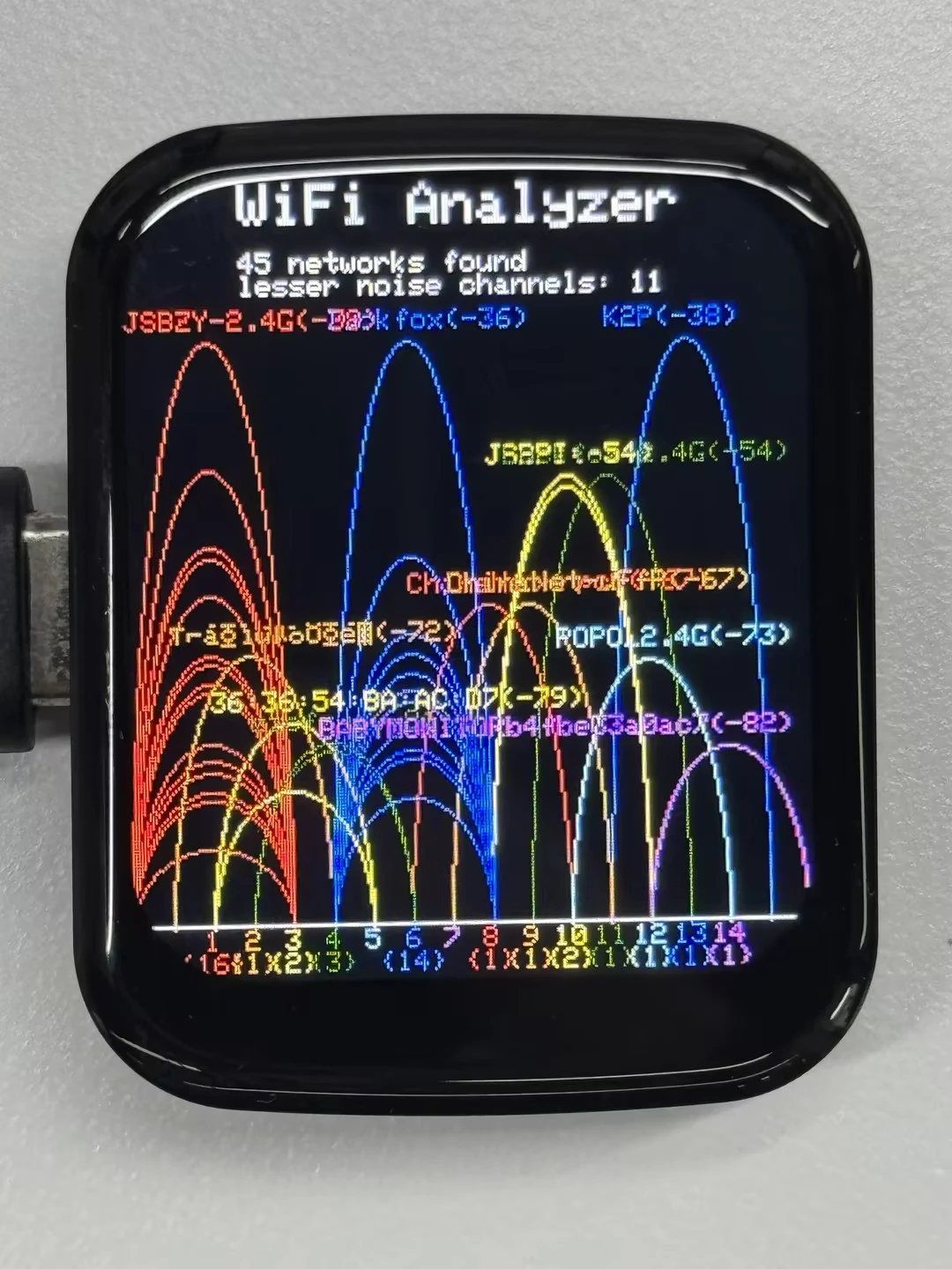
04_GFX_ESPWiFiAnalyzer
本示例演示了在 ST7789 显示器上绘制 WiFi 频段信号强度示例,实现 WiFi 分析器的功能。
代码
04_GFX_ESPWiFiAnalyzer.ino
#include <Arduino.h>
#include "Arduino_GFX_Library.h"
#include "pin_config.h"
#include <Wire.h>
#include "HWCDC.h"
Arduino_DataBus *bus = new Arduino_ESP32SPI(LCD_DC, LCD_CS, LCD_SCK, LCD_MOSI);
Arduino_GFX *gfx = new Arduino_ST7789(bus, LCD_RST /* RST */,
0 /* rotation */, true /* IPS */, LCD_WIDTH, LCD_HEIGHT, 0, 20, 0, 0);
#if defined(ESP32)
#include "WiFi.h"
#else
#include "ESP8266WiFi.h"
#define log_i(format, ...) Serial.printf(format, ##__VA_ARGS__)
#endif
int16_t w, h, text_size, banner_height, graph_baseline, graph_height, channel_width, signal_width;
// RSSI RANGE
#define RSSI_CEILING -40
#define RSSI_FLOOR -100
// Channel color mapping from channel 1 to 14
uint16_t channel_color[] = {
RGB565_RED, RGB565_ORANGE, RGB565_YELLOW, RGB565_GREEN, RGB565_CYAN, RGB565_BLUE, RGB565_MAGENTA,
RGB565_RED, RGB565_ORANGE, RGB565_YELLOW, RGB565_GREEN, RGB565_CYAN, RGB565_BLUE, RGB565_MAGENTA
};
uint8_t scan_count = 0;
bool has_scan_result = false;
static constexpr int16_t BANNER_TEXT_X = 40;
void drawScanningStatus() {
gfx->fillRect(0, banner_height, w, h - banner_height, RGB565_BLACK);
gfx->setTextSize(1);
gfx->setTextColor(RGB565_WHITE);
gfx->setCursor(BANNER_TEXT_X, banner_height);
gfx->print("Scanning WiFi...");
gfx->setTextColor(RGB565_LIGHTGREY);
gfx->setCursor(BANNER_TEXT_X, banner_height + 10);
gfx->print("Please wait");
// Draw the channel axis immediately so the screen looks alive while the
// synchronous WiFi scan is running.
gfx->drawFastHLine(0, graph_baseline, gfx->width(), RGB565_DARKGREY);
for (int32_t channel = 1; channel <= 14; channel++) {
int16_t idx = channel - 1;
int16_t offset = (channel + 1) * channel_width;
gfx->setTextColor(channel_color[idx]);
gfx->setCursor(offset - ((channel < 10) ? 3 : 6), graph_baseline + 2);
gfx->print(channel);
}
}
void setup() {
Serial.begin(115200);
// Serial.setDebugOutput(true);
// while(!Serial);
Serial.println("Arduino_GFX ESP WiFi Analyzer example");
// Set WiFi to station mode and disconnect from an AP if it was previously connected
WiFi.mode(WIFI_STA);
WiFi.disconnect();
delay(100);
#ifdef GFX_EXTRA_PRE_INIT
GFX_EXTRA_PRE_INIT();
#endif
#if defined(LCD_PWR_PIN)
pinMode(LCD_PWR_PIN, OUTPUT); // sets the pin as output
digitalWrite(LCD_PWR_PIN, HIGH); // power on
#endif
// Init Display
if (!gfx->begin()) {
Serial.println("gfx->begin() failed!");
}
w = gfx->width();
h = gfx->height();
text_size = (h < 200) ? 1 : 2;
banner_height = text_size * 3 * 4;
graph_baseline = h - 20; // minus 2 text lines
graph_height = graph_baseline - banner_height - 30; // minus 3 text lines
channel_width = w / 17;
signal_width = channel_width * 2;
pinMode(LCD_BL, OUTPUT);
digitalWrite(LCD_BL, HIGH);
// init banner
gfx->setTextSize(text_size);
gfx->fillScreen(RGB565_BLACK);
gfx->setTextColor(RGB565_RED);
gfx->setCursor(BANNER_TEXT_X, 0);
// gfx->print("ESP");
gfx->setTextColor(RGB565_WHITE);
gfx->print("WiFi Analyzer");
}
bool matchBssidPrefix(uint8_t *a, uint8_t *b) {
for (uint8_t i = 0; i < 5; i++) { // only compare first 5 bytes
if (a[i] != b[i]) {
return false;
}
}
return true;
}
void loop() {
uint8_t ap_count_list[] = { 0, 0, 0, 0, 0, 0, 0, 0, 0, 0, 0, 0, 0, 0 };
int32_t noise_list[] = { RSSI_FLOOR, RSSI_FLOOR, RSSI_FLOOR, RSSI_FLOOR, RSSI_FLOOR, RSSI_FLOOR, RSSI_FLOOR, RSSI_FLOOR, RSSI_FLOOR, RSSI_FLOOR, RSSI_FLOOR, RSSI_FLOOR, RSSI_FLOOR, RSSI_FLOOR };
int32_t peak_list[] = { RSSI_FLOOR, RSSI_FLOOR, RSSI_FLOOR, RSSI_FLOOR, RSSI_FLOOR, RSSI_FLOOR, RSSI_FLOOR, RSSI_FLOOR, RSSI_FLOOR, RSSI_FLOOR, RSSI_FLOOR, RSSI_FLOOR, RSSI_FLOOR, RSSI_FLOOR };
int16_t peak_id_list[] = { -1, -1, -1, -1, -1, -1, -1, -1, -1, -1, -1, -1, -1, -1 };
int32_t channel;
int16_t idx;
int32_t rssi;
uint8_t *bssid;
String ssid;
uint16_t color;
int16_t height, offset, text_width;
if (!has_scan_result) {
drawScanningStatus();
}
// WiFi.scanNetworks will return the number of networks found
#if defined(ESP32)
int n = WiFi.scanNetworks(false /* async */, true /* show_hidden */, true /* passive */, 500 /* max_ms_per_chan */);
#else
int n = WiFi.scanNetworks(false /* async */, true /* show_hidden */);
#endif
// clear old graph
gfx->fillRect(0, banner_height, w, h - banner_height, RGB565_BLACK);
gfx->setTextSize(1);
if (n == 0) {
gfx->setTextColor(RGB565_WHITE);
gfx->setCursor(0, banner_height);
gfx->println("no networks found");
} else {
for (int i = 0; i < n; i++) {
channel = WiFi.channel(i);
idx = channel - 1;
rssi = WiFi.RSSI(i);
bssid = WiFi.BSSID(i);
// channel peak stat
if (peak_list[idx] < rssi) {
peak_list[idx] = rssi;
peak_id_list[idx] = i;
}
// check signal come from same AP
bool duplicate_SSID = false;
for (int j = 0; j < i; j++) {
if ((WiFi.channel(j) == channel) && matchBssidPrefix(WiFi.BSSID(j), bssid)) {
duplicate_SSID = true;
break;
}
}
if (!duplicate_SSID) {
ap_count_list[idx]++;
// noise stat
int32_t noise = rssi - RSSI_FLOOR;
noise *= noise;
if (channel > 4) {
noise_list[idx - 4] += noise;
}
if (channel > 3) {
noise_list[idx - 3] += noise;
}
if (channel > 2) {
noise_list[idx - 2] += noise;
}
if (channel > 1) {
noise_list[idx - 1] += noise;
}
noise_list[idx] += noise;
if (channel < 14) {
noise_list[idx + 1] += noise;
}
if (channel < 13) {
noise_list[idx + 2] += noise;
}
if (channel < 12) {
noise_list[idx + 3] += noise;
}
if (channel < 11) {
noise_list[idx + 4] += noise;
}
}
}
// plot found WiFi info
for (int i = 0; i < n; i++) {
channel = WiFi.channel(i);
idx = channel - 1;
rssi = WiFi.RSSI(i);
color = channel_color[idx];
height = constrain(map(rssi, RSSI_FLOOR, RSSI_CEILING, 1, graph_height), 1, graph_height);
offset = (channel + 1) * channel_width;
// trim rssi with RSSI_FLOOR
if (rssi < RSSI_FLOOR) {
rssi = RSSI_FLOOR;
}
// plot chart
// gfx->drawLine(offset, graph_baseline - height, offset - signal_width, graph_baseline + 1, color);
// gfx->drawLine(offset, graph_baseline - height, offset + signal_width, graph_baseline + 1, color);
gfx->startWrite();
gfx->writeEllipseHelper(offset, graph_baseline + 1, signal_width, height, 0b0011, color);
gfx->endWrite();
if (i == peak_id_list[idx]) {
// Print SSID, signal strengh and if not encrypted
String ssid = WiFi.SSID(i);
if (ssid.length() == 0) {
ssid = WiFi.BSSIDstr(i);
}
text_width = (ssid.length() + 6) * 6;
if (text_width > w) {
offset = 0;
} else {
offset -= signal_width;
if ((offset + text_width) > w) {
offset = w - text_width;
}
}
gfx->setTextColor(color);
gfx->setCursor(offset, graph_baseline - 10 - height);
gfx->print(ssid);
gfx->print('(');
gfx->print(rssi);
gfx->print(')');
#if defined(ESP32)
if (WiFi.encryptionType(i) == WIFI_AUTH_OPEN)
#else
if (WiFi.encryptionType(i) == ENC_TYPE_NONE)
#endif
{
gfx->print('*');
}
}
}
}
// print WiFi stat
gfx->setTextColor(RGB565_WHITE);
gfx->setCursor(BANNER_TEXT_X, banner_height);
gfx->print(n);
gfx->print(" networks found");
gfx->setCursor(BANNER_TEXT_X, banner_height + 8);
gfx->print("lesser noise channels: ");
bool listed_first_channel = false;
int32_t min_noise = noise_list[0]; // init with channel 1 value
for (channel = 2; channel <= 11; channel++) // channels 12-14 may not available
{
idx = channel - 1;
log_i("min_noise: %d, noise_list[%d]: %d", min_noise, idx, noise_list[idx]);
if (noise_list[idx] < min_noise) {
min_noise = noise_list[idx];
}
}
for (channel = 1; channel <= 11; channel++) // channels 12-14 may not available
{
idx = channel - 1;
// check channel with min noise
if (noise_list[idx] == min_noise) {
if (!listed_first_channel) {
listed_first_channel = true;
} else {
gfx->print(", ");
}
gfx->print(channel);
}
}
// draw graph base axle
gfx->drawFastHLine(0, graph_baseline, gfx->width(), RGB565_WHITE);
for (channel = 1; channel <= 14; channel++) {
idx = channel - 1;
offset = (channel + 1) * channel_width;
gfx->setTextColor(channel_color[idx]);
gfx->setCursor(offset - ((channel < 10) ? 3 : 6), graph_baseline + 2);
gfx->print(channel);
if (ap_count_list[idx] > 0) {
gfx->setCursor(offset - ((ap_count_list[idx] < 10) ? 9 : 12), graph_baseline + 8 + 2);
gfx->print('{');
gfx->print(ap_count_list[idx]);
gfx->print('}');
}
}
has_scan_result = true;
// Wait a bit before scanning again
// delay(SCAN_INTERVAL);
#if defined(SCAN_COUNT_SLEEP)
// POWER SAVING
if (++scan_count >= SCAN_COUNT_SLEEP) {
#if defined(LCD_PWR_PIN)
pinMode(LCD_PWR_PIN, INPUT); // disable pin
#endif
#if defined(GFX_BL)
pinMode(GFX_BL, INPUT); // disable pin
#endif
#if defined(ESP32)
esp_sleep_enable_ext0_wakeup(GPIO_NUM_36, LOW);
esp_deep_sleep_start();
#else
ESP.deepSleep(0);
#endif
}
#endif // defined(SCAN_COUNT_SLEEP)
}
代码解释
-
setup():初始化串口通信; 设置 WiFi 为站点模式并断开连接; 初始化显示屏,获取屏幕尺寸并计算各种绘图参数; 设置屏幕背景为黑色,绘制居中的标题栏。
-
loop():首次扫描前调用
drawScanningStatus()显示扫描提示和信道坐标轴; 扫描 WiFi 网络并获取网络信息,包括信道、RSSI、BSSID 和 SSID; 统计每个信道上的网络数量、噪声水平和峰值信号强度; 清除旧的图形并根据扫描结果绘制新的图形,包括信号强度椭圆和网络信息文本; 分两行打印扫描到的网络数量和噪声最小的信道; 绘制图形基线和信道编号; 根据条件进入低功耗模式。
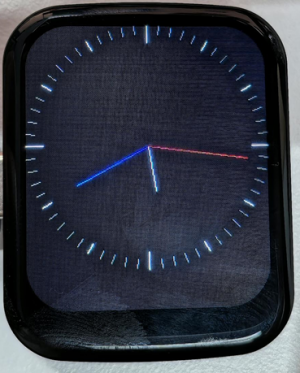
05_GFX_Clock
本示例演示了一个简单的 ST7789 时钟示例,通过简单的标记指针和时间管理实现时钟示例。
代码
05_GFX_Clock.ino
#include <Arduino.h>
#include "Arduino_GFX_Library.h"
#include "pin_config.h"
#include <Wire.h>
#include "HWCDC.h"
HWCDC USBSerial;
// SensorPCF85063 rtc;
Arduino_DataBus *bus = new Arduino_ESP32SPI(LCD_DC, LCD_CS, LCD_SCK, LCD_MOSI);
Arduino_GFX *gfx = new Arduino_ST7789(bus, LCD_RST /* RST */,
0 /* rotation */, true /* IPS */, LCD_WIDTH, LCD_HEIGHT, 0, 20, 0, 0);
#define BACKGROUND RGB565_BLACK
#define MARK_COLOR RGB565_WHITE
#define SUBMARK_COLOR RGB565_DARKGREY // RGB565_LIGHTGREY
#define HOUR_COLOR RGB565_WHITE
#define MINUTE_COLOR RGB565_BLUE // RGB565_LIGHTGREY
#define SECOND_COLOR RGB565_RED
#define SIXTIETH 0.016666667
#define TWELFTH 0.08333333
#define SIXTIETH_RADIAN 0.10471976
#define TWELFTH_RADIAN 0.52359878
#define RIGHT_ANGLE_RADIAN 1.5707963
static uint8_t conv2d(const char *p)
{
uint8_t v = 0;
return (10 * (*p - '0')) + (*++p - '0');
}
static int16_t w, h, center;
static int16_t hHandLen, mHandLen, sHandLen, markLen;
static float sdeg, mdeg, hdeg;
static int16_t osx = 0, osy = 0, omx = 0, omy = 0, ohx = 0, ohy = 0; // Saved H, M, S x & y coords
static int16_t nsx, nsy, nmx, nmy, nhx, nhy; // H, M, S x & y coords
static int16_t xMin, yMin, xMax, yMax; // redraw range
static int16_t hh, mm, ss;
static unsigned long targetTime; // next action time
static int16_t *cached_points;
static uint16_t cached_points_idx = 0;
static int16_t *last_cached_point;
void setup(void)
{
USBSerial.begin(115200);
USBSerial.println("Arduino_GFX Clock example");
// Init Display
if (!gfx->begin()) {
   USBSerial.println("gfx->begin() failed!");
 }
gfx->fillScreen(BACKGROUND);
pinMode(LCD_BL, OUTPUT);
digitalWrite(LCD_BL, HIGH);
// init LCD constant
w = gfx->width();
h = gfx->height();
if (w < h)
{
center = w / 2;
}
else
{
center = h / 2;
}
hHandLen = center * 3 / 8;
mHandLen = center * 2 / 3;
sHandLen = center * 5 / 6;
markLen = sHandLen / 6;
cached_points = (int16_t *)malloc((hHandLen + 1 + mHandLen + 1 + sHandLen + 1) * 2 * 2);
// Draw 60 clock marks
draw_round_clock_mark(
// draw_square_clock_mark(
center - markLen, center,
center - (markLen * 2 / 3), center,
center - (markLen / 2), center);
hh = conv2d(__TIME__);
mm = conv2d(__TIME__ + 3);
ss = conv2d(__TIME__ + 6);
targetTime = ((millis() / 1000) + 1) * 1000;
}
void loop()
{
unsigned long cur_millis = millis();
if (cur_millis >= targetTime)
{
targetTime += 1000;
ss++; // Advance second
if (ss == 60)
{
ss = 0;
mm++; // Advance minute
if (mm > 59)
{
mm = 0;
hh++; // Advance hour
if (hh > 23)
{
hh = 0;
}
}
}
}
// Pre-compute hand degrees, x & y coords for a fast screen update
sdeg = SIXTIETH_RADIAN * ((0.001 * (cur_millis % 1000)) + ss); // 0-59 (includes millis)
nsx = cos(sdeg - RIGHT_ANGLE_RADIAN) * sHandLen + center;
nsy = sin(sdeg - RIGHT_ANGLE_RADIAN) * sHandLen + center;
if ((nsx != osx) || (nsy != osy))
{
mdeg = (SIXTIETH * sdeg) + (SIXTIETH_RADIAN * mm); // 0-59 (includes seconds)
hdeg = (TWELFTH * mdeg) + (TWELFTH_RADIAN * hh); // 0-11 (includes minutes)
mdeg -= RIGHT_ANGLE_RADIAN;
hdeg -= RIGHT_ANGLE_RADIAN;
nmx = cos(mdeg) * mHandLen + center;
nmy = sin(mdeg) * mHandLen + center;
nhx = cos(hdeg) * hHandLen + center;
nhy = sin(hdeg) * hHandLen + center;
// redraw hands
redraw_hands_cached_draw_and_erase();
ohx = nhx;
ohy = nhy;
omx = nmx;
omy = nmy;
osx = nsx;
osy = nsy;
delay(1);
}
}
void draw_round_clock_mark(int16_t innerR1, int16_t outerR1, int16_t innerR2, int16_t outerR2, int16_t innerR3, int16_t outerR3)
{
float x, y;
int16_t x0, x1, y0, y1, innerR, outerR;
uint16_t c;
for (uint8_t i = 0; i < 60; i++)
{
if ((i % 15) == 0)
{
innerR = innerR1;
outerR = outerR1;
c = MARK_COLOR;
}
else if ((i % 5) == 0)
{
innerR = innerR2;
outerR = outerR2;
c = MARK_COLOR;
}
else
{
innerR = innerR3;
outerR = outerR3;
c = SUBMARK_COLOR;
}
mdeg = (SIXTIETH_RADIAN * i) - RIGHT_ANGLE_RADIAN;
x = cos(mdeg);
y = sin(mdeg);
x0 = x * outerR + center;
y0 = y * outerR + center;
x1 = x * innerR + center;
y1 = y * innerR + center;
gfx->drawLine(x0, y0, x1, y1, c);
}
}
void draw_square_clock_mark(int16_t innerR1, int16_t outerR1, int16_t innerR2, int16_t outerR2, int16_t innerR3, int16_t outerR3)
{
float x, y;
int16_t x0, x1, y0, y1, innerR, outerR;
uint16_t c;
for (uint8_t i = 0; i < 60; i++)
{
if ((i % 15) == 0)
{
innerR = innerR1;
outerR = outerR1;
c = MARK_COLOR;
}
else if ((i % 5) == 0)
{
innerR = innerR2;
outerR = outerR2;
c = MARK_COLOR;
}
else
{
innerR = innerR3;
outerR = outerR3;
c = SUBMARK_COLOR;
}
if ((i >= 53) || (i < 8))
{
x = tan(SIXTIETH_RADIAN * i);
x0 = center + (x * outerR);
y0 = center + (1 - outerR);
x1 = center + (x * innerR);
y1 = center + (1 - innerR);
}
else if (i < 23)
{
y = tan((SIXTIETH_RADIAN * i) - RIGHT_ANGLE_RADIAN);
x0 = center + (outerR);
y0 = center + (y * outerR);
x1 = center + (innerR);
y1 = center + (y * innerR);
}
else if (i < 38)
{
x = tan(SIXTIETH_RADIAN * i);
x0 = center - (x * outerR);
y0 = center + (outerR);
x1 = center - (x * innerR);
y1 = center + (innerR);
}
else if (i < 53)
{
y = tan((SIXTIETH_RADIAN * i) - RIGHT_ANGLE_RADIAN);
x0 = center + (1 - outerR);
y0 = center - (y * outerR);
x1 = center + (1 - innerR);
y1 = center - (y * innerR);
}
gfx->drawLine(x0, y0, x1, y1, c);
}
}
void redraw_hands_cached_draw_and_erase() {
    gfx->startWrite();
    draw_and_erase_cached_line(center, center, nsx, nsy, SECOND_COLOR, cached_points, sHandLen + 1, false, false);
    draw_and_erase_cached_line(center, center, nhx, nhy, HOUR_COLOR, cached_points + ((sHandLen + 1) * 2), hHandLen + 1, true, false);
    draw_and_erase_cached_line(center, center, nmx, nmy, MINUTE_COLOR, cached_points + ((sHandLen + 1 + hHandLen + 1) * 2), mHandLen + 1, true, true);
    gfx->endWrite();
}
void draw_and_erase_cached_line(int16_t x0, int16_t y0, int16_t x1, int16_t y1, int16_t color, int16_t *cache, int16_t cache_len, bool cross_check_second, bool cross_check_hour)
{
#if defined(ESP8266)
yield();
#endif
bool steep = _diff(y1, y0) > _diff(x1, x0);
if (steep)
{
_swap_int16_t(x0, y0);
_swap_int16_t(x1, y1);
}
int16_t dx, dy;
dx = _diff(x1, x0);
dy = _diff(y1, y0);
int16_t err = dx / 2;
int8_t xstep = (x0 < x1) ? 1 : -1;
int8_t ystep = (y0 < y1) ? 1 : -1;
x1 += xstep;
int16_t x, y, ox, oy;
for (uint16_t i = 0; i <= dx; i++)
{
if (steep)
{
x = y0;
y = x0;
}
else
{
x = x0;
y = y0;
}
ox = *(cache + (i * 2));
oy = *(cache + (i * 2) + 1);
if ((x == ox) && (y == oy))
{
if (cross_check_second || cross_check_hour)
{
write_cache_pixel(x, y, color, cross_check_second, cross_check_hour);
}
}
else
{
write_cache_pixel(x, y, color, cross_check_second, cross_check_hour);
if ((ox > 0) || (oy > 0))
{
write_cache_pixel(ox, oy, BACKGROUND, cross_check_second, cross_check_hour);
}
*(cache + (i * 2)) = x;
*(cache + (i * 2) + 1) = y;
}
if (err < dy)
{
y0 += ystep;
err += dx;
}
err -= dy;
x0 += xstep;
}
for (uint16_t i = dx + 1; i < cache_len; i++)
{
ox = *(cache + (i * 2));
oy = *(cache + (i * 2) + 1);
if ((ox > 0) || (oy > 0))
{
write_cache_pixel(ox, oy, BACKGROUND, cross_check_second, cross_check_hour);
}
*(cache + (i * 2)) = 0;
*(cache + (i * 2) + 1) = 0;
}
}
void write_cache_pixel(int16_t x, int16_t y, int16_t color, bool cross_check_second, bool cross_check_hour)
{
int16_t *cache = cached_points;
if (cross_check_second)
{
for (uint16_t i = 0; i <= sHandLen; i++)
{
if ((x == *(cache++)) && (y == *(cache)))
{
return;
}
cache++;
}
}
if (cross_check_hour)
{
cache = cached_points + ((sHandLen + 1) * 2);
for (uint16_t i = 0; i <= hHandLen; i++)
{
if ((x == *(cache++)) && (y == *(cache)))
{
return;
}
cache++;
}
}
gfx->writePixel(x, y, color);
}
代码解释
-
时针、分针、秒针的绘制 :
void redraw_hands_cached_draw_and_erase() {gfx->startWrite();draw_and_erase_cached_line(center, center, nsx, nsy, SECOND_COLOR, cached_points, sHandLen + 1, false, false);draw_and_erase_cached_line(center, center, nhx, nhy, HOUR_COLOR, cached_points + ((sHandLen + 1) * 2), hHandLen + 1, true, false);draw_and_erase_cached_line(center, center, nmx, nmy, MINUTE_COLOR, cached_points + ((sHandLen + 1 + hHandLen + 1) * 2), mHandLen + 1, true, true);gfx->endWrite();}
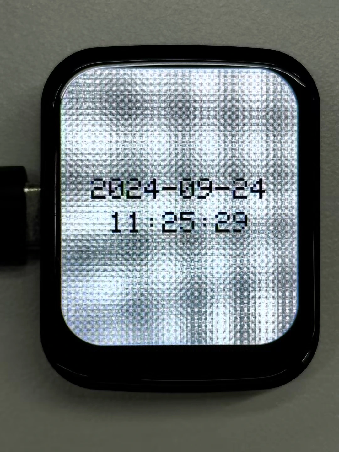
06_GFX_PCF85063_simpleTime
本示例演示了使用 PCF85063 RTC 模块在 ST7789 显示屏上显示当前时间,每秒检索时间并仅在时间发生变化时更新显示。
代码
06_GFX_PCF85063_simpleTime.ino
#include <Arduino.h>
#include "Arduino_GFX_Library.h"
#include "pin_config.h"
#include "SensorPCF85063.hpp"
#include <Wire.h>

#include "HWCDC.h"
HWCDC USBSerial;

SensorPCF85063 rtc;
uint32_t lastMillis;
char previousTimeString[20] = "";
Arduino_DataBus *bus = new Arduino_ESP32SPI(LCD_DC, LCD_CS, LCD_SCK, LCD_MOSI);

Arduino_GFX *gfx = new Arduino_ST7789(bus, LCD_RST /* RST */,
                                      0 /* rotation */, true /* IPS */, LCD_WIDTH, LCD_HEIGHT, 0, 20, 0, 0);

const uint8_t TEXT_SIZE = 3;
const int16_t FONT_WIDTH = 6;
const int16_t FONT_HEIGHT = 8;
const int16_t LINE_GAP = 10;

int16_t getCenteredX(const char *text, uint8_t textSize) {
  int16_t textWidth = strlen(text) * FONT_WIDTH * textSize;
  int16_t x = (LCD_WIDTH - textWidth) / 2;
  return x > 0 ? x : 0;
}

int16_t getTextBlockY() {
  int16_t lineHeight = FONT_HEIGHT * TEXT_SIZE;
  int16_t totalHeight = (lineHeight * 2) + LINE_GAP;
  return (LCD_HEIGHT - totalHeight) / 2;
}

void drawCenteredText(const char *text, int16_t y) {
  gfx->setCursor(getCenteredX(text, TEXT_SIZE), y);
  gfx->println(text);
}

void setup() {
  USBSerial.begin(115200);
  if (!rtc.begin(Wire, IIC_SDA, IIC_SCL)) {
    USBSerial.println("Failed to find PCF85063 - check your wiring!");
    while (1) {
      delay(1000);
    }
  }

  uint16_t year = 2024;
  uint8_t month = 9;
  uint8_t day = 24;
  uint8_t hour = 11;
  uint8_t minute = 24;
  uint8_t second = 30;

  rtc.setDateTime(year, month, day, hour, minute, second);
  gfx->begin();
  gfx->fillScreen(RGB565_WHITE);
  pinMode(LCD_BL, OUTPUT);
  digitalWrite(LCD_BL, HIGH);
}

void loop() {

  if (millis() - lastMillis > 1000) {
    lastMillis = millis();

    RTC_DateTime datetime = rtc.getDateTime();

    char dateString[11];
    char timeString[9];
    char dateTimeString[20];

    sprintf(dateString, "%04d-%02d-%02d", datetime.getYear(), datetime.getMonth(), datetime.getDay());
    sprintf(timeString, "%02d:%02d:%02d", datetime.getHour(), datetime.getMinute(), datetime.getSecond());
    sprintf(dateTimeString, "%s %s", dateString, timeString);

    // Only update the time if it has changed
    if (strcmp(dateTimeString, previousTimeString) != 0) {
      int16_t lineHeight = FONT_HEIGHT * TEXT_SIZE;
      int16_t dateY = getTextBlockY();
      int16_t timeY = dateY + lineHeight + LINE_GAP;

      gfx->fillRect(0, dateY - 4, LCD_WIDTH, (lineHeight * 2) + LINE_GAP + 8, RGB565_WHITE);
      gfx->setTextColor(RGB565_BLACK);
      gfx->setTextSize(TEXT_SIZE);

      drawCenteredText(dateString, dateY);
      drawCenteredText(timeString, timeY);

      strcpy(previousTimeString, dateTimeString);
    }
  }
}
代码解释
loop():- 首先获取当前时间,通过
getYear()、getMonth()等接口读取日期和时分秒; - 分别生成日期字符串和时间字符串,并组合成
dateTimeString用于判断显示内容是否变化; - 当日期或时间发生变化时,只清除中间文本区域,避免整屏闪烁;
- 使用
getTextBlockY()计算两行文本整体居中的起点,再通过drawCenteredText()分两行显示日期和时间; - 将当前日期时间字符串复制到
previousTimeString,以便下次判断时间是否变化。
- 首先获取当前时间,通过
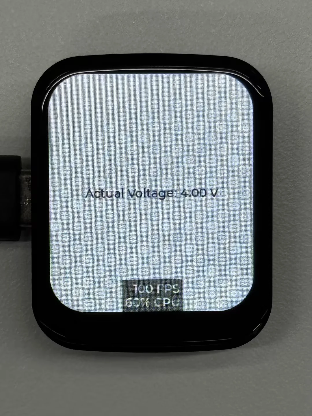
07_LVGL_Measuring_voltage
本示例展示如何使用 LVGL 库和 Arduino GFX 库,实现显示屏文本更新和电压测量。代码初始化了 ST7789 显示屏,在显示屏中心创建一个标签,并周期性地读取电压分压器的实际电压值,更新标签以显示最新的电压信息。
代码
07_LVGL_Measuring_voltage.ino
#include <lvgl.h>
#include "Arduino_GFX_Library.h"
#include "lv_conf.h"
#include "demos/lv_demos.h"
#include "pin_config.h"

/* Using LVGL with Arduino requires some extra steps:
 * Be sure to read the docs here: https://lvgl.io/docs/open/integration/frameworks/arduino  */

#define EXAMPLE_LVGL_TICK_PERIOD_MS 2

/* Change to your screen resolution */
static const uint16_t screenWidth = 240;
static const uint16_t screenHeight = 280;

static lv_disp_draw_buf_t draw_buf;
static lv_color_t buf[screenWidth * screenHeight / 10];

const int voltageDividerPin = 1;  // GPIO1 pin
float vRef = 3.3;                 // Power supply voltage of ESP32-S3 (unit: volts)
float R1 = 200000.0;              // Resistance value of the first resistor (unit: ohms)
float R2 = 100000.0;              // Resistance value of the second resistor (unit: ohms)

lv_obj_t *label;  // Global label object

Arduino_DataBus *bus = new Arduino_ESP32SPI(LCD_DC, LCD_CS, LCD_SCK, LCD_MOSI);

Arduino_GFX *gfx = new Arduino_ST7789(bus, LCD_RST /* RST */,
                                      0 /* rotation */, true /* IPS */, LCD_WIDTH, LCD_HEIGHT, 0, 20, 0, 0);

#if LV_USE_LOG!= 0
/* Serial debugging */
void my_print(const char *buf) {
  Serial.printf(buf);
  Serial.flush();
}
#endif

/* Display flushing */
void my_disp_flush(lv_disp_drv_t *disp, const lv_area_t *area, lv_color_t *color_p) {
  uint32_t w = (area->x2 - area->x1 + 1);
  uint32_t h = (area->y2 - area->y1 + 1);

#if (LV_COLOR_16_SWAP!= 0)
  gfx->draw16bitBeRGBBitmap(area->x1, area->y1, (uint16_t *)&color_p->full, w, h);
#else
  gfx->draw16bitRGBBitmap(area->x1, area->y1, (uint16_t *)&color_p->full, w, h);
#endif

  lv_disp_flush_ready(disp);
}

void example_increase_lvgl_tick(void *arg) {
  /* Tell LVGL how many milliseconds has elapsed */
  lv_tick_inc(EXAMPLE_LVGL_TICK_PERIOD_MS);
}

static uint8_t count = 0;
void example_increase_reboot(void *arg) {
  count++;
  if (count == 30) {
    esp_restart();
  }
}

void setup() {
  Serial.begin(115200); /* prepare for possible serial debug */
  pinMode(voltageDividerPin, INPUT);

  String LVGL_Arduino = "Hello Arduino! ";
  LVGL_Arduino += String('V') + lv_version_major() + "." + lv_version_minor() + "." + lv_version_patch();

  Serial.println(LVGL_Arduino);
  Serial.println("I am LVGL_Arduino");

  lv_init();

#if LV_USE_LOG!= 0
  lv_log_register_print_cb(my_print); /* register print function for debugging */
#endif

  gfx->begin();
  pinMode(LCD_BL, OUTPUT);
  digitalWrite(LCD_BL, HIGH);

  lv_disp_draw_buf_init(&draw_buf, buf, NULL, screenWidth * screenHeight / 10);

  /* Initialize the display */
  static lv_disp_drv_t disp_drv;
  lv_disp_drv_init(&disp_drv);
  /* Change the following line to your display resolution */
  disp_drv.hor_res = screenWidth;
  disp_drv.ver_res = screenHeight;
  disp_drv.flush_cb = my_disp_flush;
  disp_drv.draw_buf = &draw_buf;
  lv_disp_drv_register(&disp_drv);

  const esp_timer_create_args_t lvgl_tick_timer_args = {
   .callback = &example_increase_lvgl_tick,
   .name = "lvgl_tick"
  };

  const esp_timer_create_args_t reboot_timer_args = {
   .callback = &example_increase_reboot,
   .name = "reboot"
  };

  esp_timer_handle_t lvgl_tick_timer = NULL;
  esp_timer_create(&lvgl_tick_timer_args, &lvgl_tick_timer);
  esp_timer_start_periodic(lvgl_tick_timer, EXAMPLE_LVGL_TICK_PERIOD_MS * 1000);

  // esp_timer_handle_t reboot_timer = NULL;
  // esp_timer_create(&reboot_timer_args, &reboot_timer);
  // esp_timer_start_periodic(reboot_timer, 2000 * 1000);

  /* Create label */
  label = lv_label_create(lv_scr_act());
  lv_label_set_text(label, "Initializing...");
  lv_obj_align(label, LV_ALIGN_CENTER, 0, 0);

  Serial.println("Setup done");
}

void loop() {
  lv_timer_handler(); /* let the GUI do its work */
  delay(5);

  // Read ADC value
  int adcValue = analogRead(voltageDividerPin);

  // Convert to voltage
  float voltage = (float)adcValue * (vRef / 4095.0);

  // Apply the voltage divider formula to calculate the actual voltage
  float actualVoltage = voltage * ((R1 + R2) / R2);

  // Print the actual voltage
  Serial.print("Actual Voltage: ");
  Serial.print(actualVoltage);
  Serial.println(" V");

  // Update label content
  String voltageStr = "Actual Voltage: " + String(actualVoltage) + " V";
  lv_label_set_text(label, voltageStr.c_str());
}
代码解释
my_print():用于 LVGL 的日志输出,如果启用了 LVGL 的日志功能,这个函数会将日志信息打印到串口my_disp_flush():负责将 LVGL 的绘图缓冲区内容刷新到显示屏上example_increase_lvgl_tick():定时器回调函数,用于通知 LVGL 时间的流逝example_increase_reboot():另一个定时器回调函数,用于计数,达到一定次数后可能触发系统重启
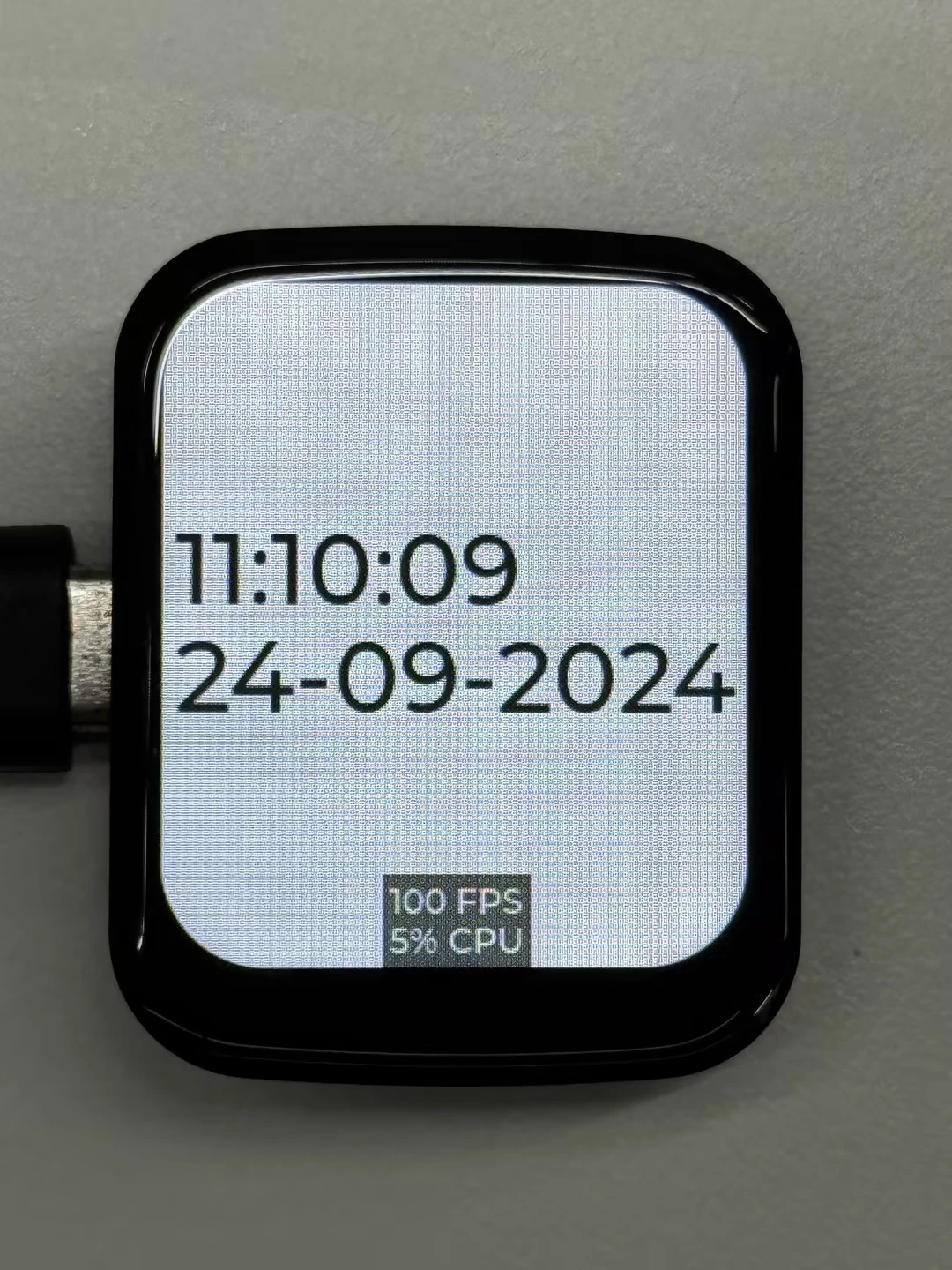
08_LVGL_PCF85063_simpleTime
本示例演示了在 LVGL 下使用 PCF85063 RTC 模块在 ST7789 显示屏上显示当前时间,每秒检索时间并仅在时间发生变化时更新显示。
代码
08_LVGL_PCF85063_simpleTime.ino
#include <lvgl.h>
#include "Arduino_GFX_Library.h"
#include "pin_config.h"
#include "lv_conf.h"
#include <Wire.h>
#include <SPI.h>
#include <Arduino.h>
#include "SensorPCF85063.hpp"
#include "HWCDC.h"

HWCDC USBSerial;
#define EXAMPLE_LVGL_TICK_PERIOD_MS 2

static lv_disp_draw_buf_t draw_buf;
static lv_color_t buf[LCD_WIDTH * LCD_HEIGHT / 10];

lv_obj_t *label;  // Global label object
SensorPCF85063 rtc;
uint32_t lastMillis;

Arduino_DataBus *bus = new Arduino_ESP32SPI(LCD_DC, LCD_CS, LCD_SCK, LCD_MOSI);

Arduino_GFX *gfx = new Arduino_ST7789(bus, LCD_RST /* RST */,
                                      0 /* rotation */, true /* IPS */, LCD_WIDTH, LCD_HEIGHT, 0, 20, 0, 0);
#if LV_USE_LOG != 0
/* Serial debugging */
void my_print(const char *buf) {
  USBSerial.printf(buf);
  USBSerial.flush();
}
#endif

/* Display flushing */
void my_disp_flush(lv_disp_drv_t *disp, const lv_area_t *area, lv_color_t *color_p) {
  uint32_t w = (area->x2 - area->x1 + 1);
  uint32_t h = (area->y2 - area->y1 + 1);

#if (LV_COLOR_16_SWAP != 0)
  gfx->draw16bitBeRGBBitmap(area->x1, area->y1, (uint16_t *)&color_p->full, w, h);
#else
  gfx->draw16bitRGBBitmap(area->x1, area->y1, (uint16_t *)&color_p->full, w, h);
#endif

  lv_disp_flush_ready(disp);
}

void example_increase_lvgl_tick(void *arg) {
  /* Tell LVGL how many milliseconds has elapsed */
  lv_tick_inc(EXAMPLE_LVGL_TICK_PERIOD_MS);
}

static uint8_t count = 0;
void example_increase_reboot(void *arg) {
  count++;
  if (count == 30) {
    esp_restart();
  }
}

void setup() {
  USBSerial.begin(115200); /* prepare for possible serial debug */
  if (!rtc.begin(Wire, IIC_SDA, IIC_SCL)) {
    USBSerial.println("Failed to find PCF85063 - check your wiring!");
    while (1) {
      delay(1000);
    }
  }

  uint16_t year = 2024;
  uint8_t month = 9;
  uint8_t day = 24;
  uint8_t hour = 11;
  uint8_t minute = 9;
  uint8_t second = 41;

  rtc.setDateTime(year, month, day, hour, minute, second);


  gfx->begin();
  pinMode(LCD_BL, OUTPUT);
  digitalWrite(LCD_BL, HIGH);

  String LVGL_Arduino = "Hello Arduino! ";
  LVGL_Arduino += String('V') + lv_version_major() + "." + lv_version_minor() + "." + lv_version_patch();

  USBSerial.println(LVGL_Arduino);
  USBSerial.println("I am LVGL_Arduino");

  lv_init();

#if LV_USE_LOG != 0
  lv_log_register_print_cb(my_print); /* register print function for debugging */
#endif


  lv_disp_draw_buf_init(&draw_buf, buf, NULL, LCD_WIDTH * LCD_HEIGHT / 10);

  /*Initialize the display*/
  static lv_disp_drv_t disp_drv;
  lv_disp_drv_init(&disp_drv);
  /*Change the following line to your display resolution*/
  disp_drv.hor_res = LCD_WIDTH;
  disp_drv.ver_res = LCD_HEIGHT;
  disp_drv.flush_cb = my_disp_flush;
  disp_drv.draw_buf = &draw_buf;
  lv_disp_drv_register(&disp_drv);

  // lv_obj_t *label = lv_label_create(lv_scr_act());
  // lv_label_set_text(label, "Hello Ardino and LVGL!");
  // lv_obj_align(label, LV_ALIGN_CENTER, 0, 0);

  const esp_timer_create_args_t lvgl_tick_timer_args = {
    .callback = &example_increase_lvgl_tick,
    .name = "lvgl_tick"
  };

  const esp_timer_create_args_t reboot_timer_args = {
    .callback = &example_increase_reboot,
    .name = "reboot"
  };

  esp_timer_handle_t lvgl_tick_timer = NULL;
  esp_timer_create(&lvgl_tick_timer_args, &lvgl_tick_timer);
  esp_timer_start_periodic(lvgl_tick_timer, EXAMPLE_LVGL_TICK_PERIOD_MS * 1000);

  label = lv_label_create(lv_scr_act());
  lv_label_set_text(label, "Initializing...");
  lv_obj_align(label, LV_ALIGN_CENTER, 0, 0);
}

void loop() {
  lv_timer_handler(); /* let the GUI do its work */
  delay(5);

  if (millis() - lastMillis > 1000) {
    lastMillis = millis();
    RTC_DateTime datetime = rtc.getDateTime();
    USBSerial.printf(" Year :");
    USBSerial.print(datetime.getYear());
    USBSerial.printf(" Month:");
    USBSerial.print(datetime.getMonth());
    USBSerial.printf(" Day :");
    USBSerial.print(datetime.getDay());
    USBSerial.printf(" Hour:");
    USBSerial.print(datetime.getHour());
    USBSerial.printf(" Minute:");
    USBSerial.print(datetime.getMinute());
    USBSerial.printf(" Sec :");
    USBSerial.println(datetime.getSecond());

    char buf[32];
    snprintf(buf, sizeof(buf), "%02d:%02d:%02d\n%02d-%02d-%04d",
             datetime.getHour(), datetime.getMinute(), datetime.getSecond(),
             datetime.getDay(), datetime.getMonth(), datetime.getYear());

    // Update label with current time
    lv_label_set_text(label, buf);
    lv_obj_set_style_text_font(label, &lv_font_montserrat_40, LV_PART_MAIN);
  }
  delay(20);
}
代码解释
-
setup():- 初始化串口通信,以 115200 的波特率准备可能的串口调试;
- 尝试连接 PCF85063 实时时钟芯片,如果连接失败则进入死循环;
- 设置实时时钟的初始时间为 2024 年 9 月 24 日 11 时 9 分 41 秒;
- 初始化显示屏,设置屏幕亮度;
- 初始化 LVGL,并注册日志输出函数(如果启用了日志功能;
- 配置 LVGL 的显示驱动和绘图缓冲区;
- 创建定时器用于定期触发 LVGL 的时钟更新
- 创建一个标签并设置初始文本为 “Initializing...”
-
loop():- 调用
lv_timer_handler让 LVGL 处理图形界面的任务; - 每秒钟检查一次时间是否更新,如果是,则通过
RTC_DateTime的 getter 接口读取实时时钟数据,通过串口输出,并将时间格式化为特定格式后更新标签的文本内容,同时设置标签的字体为lv_font_montserrat_40。
- 调用
09_LVGL_Keys_Bee
本示例展示了如何使用 LVGL 库结合 Arduino 和 ESP32 来实现一个带有简单 GUI 交互的按键响应系统。该代码允许用户通过按键检测单击、双击和长按事件,并将相应的输出显示在连接的液晶屏幕上。
具体功能实现包括:利用触发操作在屏幕上显示 "Single Click"、"Double Click" 和 "Long Press" 字样,并在长按时启用蜂鸣器。程序通过 LVGL 的绘图功能实现屏幕刷新,并通过简单的去抖动机制提高按键识别的准确性。此外,还设置了自动重启机制用于长时间运行的设备维护。

代码
09_LVGL_Keys_Bee.ino
#error "按键失灵时,请修改 USE_NEW_PIN_CONFIG 为 1 以使用新的引脚配置。运行代码时,请注释此行,If the key fails, change USE_NEW_PIN_CONFIG to 1 to use the new pin configuration. Comment this line as you run the code"

#include <lvgl.h>
#include "Arduino_GFX_Library.h"
#include "lv_conf.h"
#include "demos/lv_demos.h"
#include "pin_config.h"
#include <Wire.h>
#include "HWCDC.h"

HWCDC USBSerial;
/*To use the built-in examples and demos of LVGL uncomment the includes below respectively.
 *You also need to copy `lvgl/examples` to `lvgl/src/examples`. Similarly for the demos `lvgl/demos` to `lvgl/src/demos`.
 Note that the `lv_examples` library is for LVGL v7 and you shouldn't install it for this version (since LVGL v8)
 as the examples and demos are now part of the main LVGL library. */

#define EXAMPLE_LVGL_TICK_PERIOD_MS 2
#define USE_NEW_PIN_CONFIG 0

#if (USE_NEW_PIN_CONFIG)
// New pin configuration
const int inputPin = 40;   // Define GPIO40 as input
const int outputPin = 41;  // Define GPIO41 as output
const int beePin = 42;     // Define GPIO42 for buzzer
#else
// Existing pin configuration
const int inputPin = 36;   // Define GPIO36 as input
const int outputPin = 35;  // Define GPIO35 as output
const int beePin = 33;     // Define GPIO33 for buzzer
#endif

bool buttonState = false;
bool lastButtonState = false;
unsigned long lastDebounceTime = 0;
unsigned long debounceDelay = 50;
unsigned long lastClickTime = 0;
unsigned long clickInterval = 500;       // Double-click interval
unsigned long longPressDuration = 1000;  // Long press duration

bool longPressDetected = false;
bool doubleClickDetected = false;
bool clickDetected = false;

/*Change to your screen resolution*/
static const uint16_t screenWidth = 240;
static const uint16_t screenHeight = 280;

static lv_disp_draw_buf_t draw_buf;
static lv_color_t buf[screenWidth * screenHeight / 10];

lv_obj_t *label;  // Global label object

Arduino_DataBus *bus = new Arduino_ESP32SPI(LCD_DC, LCD_CS, LCD_SCK, LCD_MOSI);

Arduino_GFX *gfx = new Arduino_ST7789(bus, LCD_RST /* RST */,
                                      0 /* rotation */, true /* IPS */, LCD_WIDTH, LCD_HEIGHT, 0, 20, 0, 0);

#if LV_USE_LOG != 0
/* USBSerial debugging */
void my_print(const char *buf) {
  USBSerial.printf(buf);
  USBSerial.flush();
}
#endif

/* Display flushing */
void my_disp_flush(lv_disp_drv_t *disp, const lv_area_t *area, lv_color_t *color_p) {
  uint32_t w = (area->x2 - area->x1 + 1);
  uint32_t h = (area->y2 - area->y1 + 1);

#if (LV_COLOR_16_SWAP != 0)
  gfx->draw16bitBeRGBBitmap(area->x1, area->y1, (uint16_t *)&color_p->full, w, h);
#else
  gfx->draw16bitRGBBitmap(area->x1, area->y1, (uint16_t *)&color_p->full, w, h);
#endif

  lv_disp_flush_ready(disp);
}

void example_increase_lvgl_tick(void *arg) {
  /* Tell LVGL how many milliseconds has elapsed */
  lv_tick_inc(EXAMPLE_LVGL_TICK_PERIOD_MS);
}

static uint8_t count = 0;
void example_increase_reboot(void *arg) {
  count++;
  if (count == 30) {
    esp_restart();
  }
}

void setup() {
  pinMode(inputPin, INPUT);
  pinMode(outputPin, OUTPUT);
  pinMode(beePin, OUTPUT);
  digitalWrite(outputPin, HIGH);  // Initialize output pin to HIGH

  gfx->begin();
  pinMode(LCD_BL, OUTPUT);
  digitalWrite(LCD_BL, HIGH);

  String LVGL_Arduino = "Hello Arduino! ";
  LVGL_Arduino += String('V') + lv_version_major() + "." + lv_version_minor() + "." + lv_version_patch();

  USBSerial.println(LVGL_Arduino);
  USBSerial.println("I am LVGL_Arduino");

  lv_init();

#if LV_USE_LOG != 0
  lv_log_register_print_cb(my_print); /* register print function for debugging */
#endif

  lv_disp_draw_buf_init(&draw_buf, buf, NULL, screenWidth * screenHeight / 10);

  /*Initialize the display*/
  static lv_disp_drv_t disp_drv;
  lv_disp_drv_init(&disp_drv);
  /*Change the following line to your display resolution*/
  disp_drv.hor_res = screenWidth;
  disp_drv.ver_res = screenHeight;
  disp_drv.flush_cb = my_disp_flush;
  disp_drv.draw_buf = &draw_buf;
  lv_disp_drv_register(&disp_drv);

  const esp_timer_create_args_t lvgl_tick_timer_args = {
    .callback = &example_increase_lvgl_tick,
    .name = "lvgl_tick"
  };

  const esp_timer_create_args_t reboot_timer_args = {
    .callback = &example_increase_reboot,
    .name = "reboot"
  };

  esp_timer_handle_t lvgl_tick_timer = NULL;
  esp_timer_create(&lvgl_tick_timer_args, &lvgl_tick_timer);
  esp_timer_start_periodic(lvgl_tick_timer, EXAMPLE_LVGL_TICK_PERIOD_MS * 1000);

  // esp_timer_handle_t reboot_timer = NULL;
  // esp_timer_create(&reboot_timer_args, &reboot_timer);
  // esp_timer_start_periodic(reboot_timer, 2000 * 1000);

  label = lv_label_create(lv_scr_act());
  lv_label_set_text(label, "Initializing...");
  lv_obj_align(label, LV_ALIGN_CENTER, 0, 0);

  USBSerial.println("Setup done");
}

void loop() {
  lv_timer_handler(); /* let the GUI do its work */
  delay(5);

  int reading = digitalRead(inputPin);
  // Debounce processing
  if (reading != lastButtonState) {
    lastDebounceTime = millis();
  }
  if ((millis() - lastDebounceTime) > debounceDelay) {
    if (reading != buttonState) {
      buttonState = reading;

      if (buttonState == LOW) {
        // Operation when button is pressed
        unsigned long now = millis();
        if (now - lastClickTime < clickInterval && !longPressDetected) {
          lv_label_set_text(label, "Double Click");
          // Double click detected
          printf("Double Click\n");
          doubleClickDetected = true;
        } else {
          // Single click detected
          if (!longPressDetected && !doubleClickDetected) {
            lv_label_set_text(label, "Single Click");
            printf("Single Click\n");
            clickDetected = true;
          }
        }
        lastClickTime = now;

        delay(100);  // Used to eliminate button noise
      } else {
        // Operation when button is released
        if (longPressDetected) {
          lv_label_set_text(label, "Long Press Released");

          // Set GPIO35 output to low level after long pressing the button and releasing it
          printf("Long Press Released\n");
          noTone(beePin);
          digitalWrite(outputPin, LOW);  // Set GPIO35 output to low level
          longPressDetected = false;     // Reset long press detection flag
        }
        clickDetected = false;
        doubleClickDetected = false;
      }
    }
  }

  // Check if the button is in long press state
  if (buttonState == LOW && (millis() - lastDebounceTime >= longPressDuration)) {
    lv_label_set_text(label, "Long Press");
    // Long press button
    printf("Long Press\n");
    tone(beePin, 2000);
    longPressDetected = true;     // Set long press detection flag
    clickDetected = false;        // Reset single click detection flag
    doubleClickDetected = false;  // Reset double click detection flag
  }
  lastButtonState = reading;
}
代码解释
loop():- 调用
lv_timer_handler让 LVGL 处理图形界面的任务; - 读取输入引脚的状态,进行去抖动处理;
- 根据按钮的状态(按下或释放)以及时间间隔判断是单点击、双点击还是长按事件,并更新显示屏上的标签文本以显示相应的事件信息;
- 同时,对于长按事件会触发蜂鸣器发声,释放时则停止蜂鸣器并将特定输出引脚设置为低电平。
- 调用
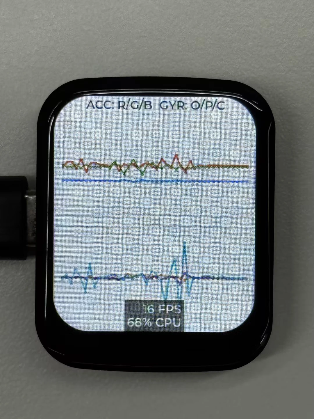
10_LVGL_QMI8658_ui
本示例演示了使用 LVGL 进行图形显示,与 QMI8658 IMU 通信以获取加速度计和陀螺仪数据。界面上方显示曲线颜色说明,屏幕中部和下部分别绘制加速度计与陀螺仪三轴数据曲线。
代码
10_LVGL_QMI8658_ui.ino
#include <lvgl.h>
#include "Arduino_GFX_Library.h"
#include "pin_config.h"
#include "lv_conf.h"
#include <Arduino.h>
#include <Wire.h>
#include <math.h>
#include "SensorQMI8658.hpp"
#include "HWCDC.h"

HWCDC USBSerial;

#define EXAMPLE_LVGL_TICK_PERIOD_MS 2
#define ACC_CHART_SCALE 100
#define GYR_CHART_SCALE 10
#define GYR_CHART_RANGE_DPS 256
#define CHART_POINT_COUNT 40
#define CHART_POINT_SIZE 2

static lv_disp_draw_buf_t draw_buf;
static lv_color_t buf[LCD_WIDTH * LCD_HEIGHT / 10];

SensorQMI8658 qmi;

IMUdata acc;
IMUdata gyr;

lv_obj_t *label;                  // Global label object
lv_obj_t *acc_chart;              // Acceleration chart object
lv_obj_t *gyr_chart;              // Gyroscope chart object
lv_chart_series_t *acc_series_x;  // Acceleration X series
lv_chart_series_t *acc_series_y;  // Acceleration Y series
lv_chart_series_t *acc_series_z;  // Acceleration Z series
lv_chart_series_t *gyr_series_x;  // Gyroscope X series
lv_chart_series_t *gyr_series_y;  // Gyroscope Y series
lv_chart_series_t *gyr_series_z;  // Gyroscope Z series

Arduino_DataBus *bus = new Arduino_ESP32SPI(LCD_DC, LCD_CS, LCD_SCK, LCD_MOSI);

Arduino_GFX *gfx = new Arduino_ST7789(bus, LCD_RST /* RST */,
                                      0 /* rotation */, true /* IPS */, LCD_WIDTH, LCD_HEIGHT, 0, 20, 0, 0);

#if LV_USE_LOG != 0
/* Serial debugging */
void my_print(const char *buf) {
  USBSerial.printf("%s", buf);
  USBSerial.flush();
}
#endif

/* Display flushing */
void my_disp_flush(lv_disp_drv_t *disp, const lv_area_t *area, lv_color_t *color_p) {
  uint32_t w = (area->x2 - area->x1 + 1);
  uint32_t h = (area->y2 - area->y1 + 1);

#if (LV_COLOR_16_SWAP != 0)
  gfx->draw16bitBeRGBBitmap(area->x1, area->y1, (uint16_t *)&color_p->full, w, h);
#else
  gfx->draw16bitRGBBitmap(area->x1, area->y1, (uint16_t *)&color_p->full, w, h);
#endif

  lv_disp_flush_ready(disp);
}

void example_increase_lvgl_tick(void *arg) {
  /* Tell LVGL how many milliseconds has elapsed */
  lv_tick_inc(EXAMPLE_LVGL_TICK_PERIOD_MS);
}

static lv_coord_t accel_to_chart_value(float value) {
  return (lv_coord_t)lroundf(value * ACC_CHART_SCALE);
}

static lv_coord_t gyro_to_chart_value(float value) {
  return (lv_coord_t)lroundf(value * GYR_CHART_SCALE);
}


void setup() {
  USBSerial.begin(115200); /* prepare for possible serial debug */

  // pinMode(LCD_EN, OUTPUT);
  // digitalWrite(LCD_EN, HIGH);

  gfx->begin();
  pinMode(LCD_BL, OUTPUT);
  pinMode(38, OUTPUT);
  digitalWrite(LCD_BL, HIGH);
  digitalWrite(38, HIGH);
  String LVGL_Arduino = "Hello Arduino! ";
  LVGL_Arduino += String('V') + lv_version_major() + "." + lv_version_minor() + "." + lv_version_patch();

  USBSerial.println(LVGL_Arduino);
  USBSerial.println("I am LVGL_Arduino");

  lv_init();

#if LV_USE_LOG != 0
  lv_log_register_print_cb(my_print); /* register print function for debugging */
#endif

  lv_disp_draw_buf_init(&draw_buf, buf, NULL, LCD_WIDTH * LCD_HEIGHT / 10);

  /*Initialize the display*/
  static lv_disp_drv_t disp_drv;
  lv_disp_drv_init(&disp_drv);
  /*Change the following line to your display resolution*/
  disp_drv.hor_res = LCD_WIDTH;
  disp_drv.ver_res = LCD_HEIGHT;
  disp_drv.flush_cb = my_disp_flush;
  disp_drv.draw_buf = &draw_buf;
  lv_disp_drv_register(&disp_drv);

  label = lv_label_create(lv_scr_act());
  lv_label_set_text(label, "Hello Arduino and LVGL!");
  lv_obj_align(label, LV_ALIGN_CENTER, 0, 0);

  const esp_timer_create_args_t lvgl_tick_timer_args = {
    .callback = &example_increase_lvgl_tick,
    .name = "lvgl_tick"
  };

  esp_timer_handle_t lvgl_tick_timer = NULL;
  esp_timer_create(&lvgl_tick_timer_args, &lvgl_tick_timer);
  esp_timer_start_periodic(lvgl_tick_timer, EXAMPLE_LVGL_TICK_PERIOD_MS * 1000);

  lv_label_set_text(label, "ACC: R/G/B  GYR: O/P/C");
  lv_obj_align(label, LV_ALIGN_TOP_MID, 0, 2);

  /* Create acceleration chart */
  acc_chart = lv_chart_create(lv_scr_act());
  lv_obj_set_size(acc_chart, 240, 122);
  lv_obj_align(acc_chart, LV_ALIGN_TOP_MID, 0, 20);
  lv_chart_set_type(acc_chart, LV_CHART_TYPE_LINE);
  lv_chart_set_range(acc_chart, LV_CHART_AXIS_PRIMARY_Y,
                     -3 * ACC_CHART_SCALE, 3 * ACC_CHART_SCALE);
  lv_chart_set_point_count(acc_chart, CHART_POINT_COUNT);
  lv_obj_set_style_size(acc_chart, CHART_POINT_SIZE, LV_PART_INDICATOR);
  acc_series_x = lv_chart_add_series(acc_chart, lv_palette_main(LV_PALETTE_RED), LV_CHART_AXIS_PRIMARY_Y);
  acc_series_y = lv_chart_add_series(acc_chart, lv_palette_main(LV_PALETTE_GREEN), LV_CHART_AXIS_PRIMARY_Y);
  acc_series_z = lv_chart_add_series(acc_chart, lv_palette_main(LV_PALETTE_BLUE), LV_CHART_AXIS_PRIMARY_Y);

  /* Create gyroscope chart */
  gyr_chart = lv_chart_create(lv_scr_act());
  lv_obj_set_size(gyr_chart, 240, 122);
  lv_obj_align(gyr_chart, LV_ALIGN_TOP_MID, 0, 154);
  lv_chart_set_type(gyr_chart, LV_CHART_TYPE_LINE);
  lv_chart_set_range(gyr_chart, LV_CHART_AXIS_PRIMARY_Y,
                     -GYR_CHART_RANGE_DPS * GYR_CHART_SCALE,
                     GYR_CHART_RANGE_DPS * GYR_CHART_SCALE);
  lv_chart_set_point_count(gyr_chart, CHART_POINT_COUNT);
  lv_obj_set_style_size(gyr_chart, CHART_POINT_SIZE, LV_PART_INDICATOR);
  gyr_series_x = lv_chart_add_series(gyr_chart, lv_palette_main(LV_PALETTE_ORANGE), LV_CHART_AXIS_PRIMARY_Y);
  gyr_series_y = lv_chart_add_series(gyr_chart, lv_palette_main(LV_PALETTE_PURPLE), LV_CHART_AXIS_PRIMARY_Y);
  gyr_series_z = lv_chart_add_series(gyr_chart, lv_palette_main(LV_PALETTE_CYAN), LV_CHART_AXIS_PRIMARY_Y);

  USBSerial.println("Setup done");

  if (!qmi.begin(Wire, QMI8658_L_SLAVE_ADDRESS, IIC_SDA, IIC_SCL)) {

    while (1) {
      delay(1000);
    }
  }

  /* Get chip id */
  USBSerial.println(qmi.getChipID());

  qmi.configAccelerometer(
    SensorQMI8658::ACC_RANGE_4G,
    SensorQMI8658::ACC_ODR_1000Hz,
    SensorQMI8658::LPF_MODE_0);

  qmi.configGyroscope(
    SensorQMI8658::GYR_RANGE_256DPS,
    SensorQMI8658::GYR_ODR_896_8Hz,
    SensorQMI8658::LPF_MODE_3);

  qmi.enableGyroscope();
  qmi.enableAccelerometer();

  qmi.dumpCtrlRegister();

  USBSerial.println("Read data now...");
}

void loop() {
  lv_timer_handler(); /* let the GUI do its work */
  delay(5);

  if (qmi.getDataReady()) {
    if (qmi.getAccelerometer(acc.x, acc.y, acc.z)) {
      USBSerial.print("{ACCEL: ");
      USBSerial.print(acc.x);
      USBSerial.print(",");
      USBSerial.print(acc.y);
      USBSerial.print(",");
      USBSerial.print(acc.z);
      USBSerial.println("}");

      // Update chart with new accelerometer data
      lv_chart_set_next_value(acc_chart, acc_series_x, accel_to_chart_value(acc.x));
      lv_chart_set_next_value(acc_chart, acc_series_y, accel_to_chart_value(acc.y));
      lv_chart_set_next_value(acc_chart, acc_series_z, accel_to_chart_value(acc.z));
    }

    if (qmi.getGyroscope(gyr.x, gyr.y, gyr.z)) {
      USBSerial.print("{GYRO: ");
      USBSerial.print(gyr.x);
      USBSerial.print(",");
      USBSerial.print(gyr.y);
      USBSerial.print(",");
      USBSerial.print(gyr.z);
      USBSerial.println("}");

      // Update chart with new gyroscope data
      lv_chart_set_next_value(gyr_chart, gyr_series_x, gyro_to_chart_value(gyr.x));
      lv_chart_set_next_value(gyr_chart, gyr_series_y, gyro_to_chart_value(gyr.y));
      lv_chart_set_next_value(gyr_chart, gyr_series_z, gyro_to_chart_value(gyr.z));
    }
  }
  delay(20);  // Increase the frequency of data polling
}
代码解释
-
my_disp_flush():- 这个函数是 LVGL 显示驱动的刷新函数。它负责将 LVGL 的绘图缓冲区内容刷新到显示屏上;
- 根据不同的颜色格式设置,调用
gfx对象的相应函数来绘制位图到特定的区域; - 最后通知 LVGL 显示刷新已完成。
-
loop():- 调用
lv_timer_handler让 LVGL 处理图形界面的任务; - 检查
qmi(QMI8658 传感器对象)是否有新数据准备好。如果有,尝试获取加速度数据和陀螺仪数据,并通过串口输出; - 将加速度数据按
ACC_CHART_SCALE缩放后更新到上方曲线图,以便实时显示加速度在三个轴上的变化情况; - 将陀螺仪数据按
GYR_CHART_SCALE缩放后更新到下方曲线图,以便实时显示角速度在三个轴上的变化情况; - 通过
delay(20)增加数据轮询的频率,以确保及时获取传感器数据并更新显示。
- 调用
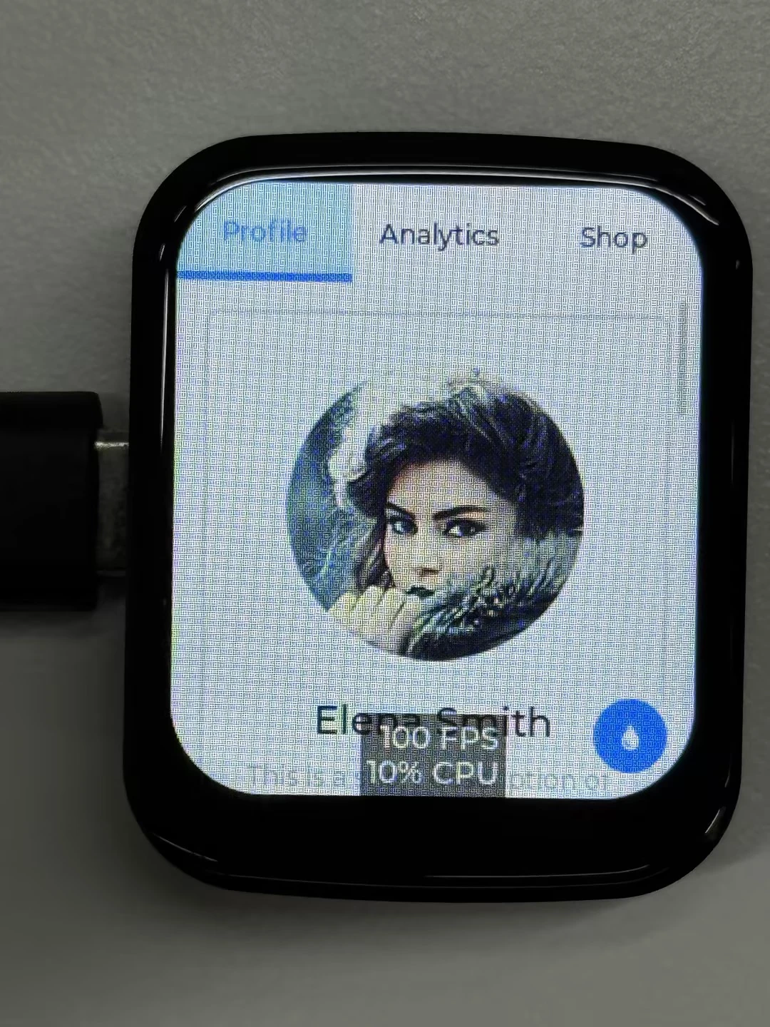
11_LVGL_Arduino
本示例演示了 LVGL Widgets 示例,动态状态下帧率可达 20~30 帧
 | 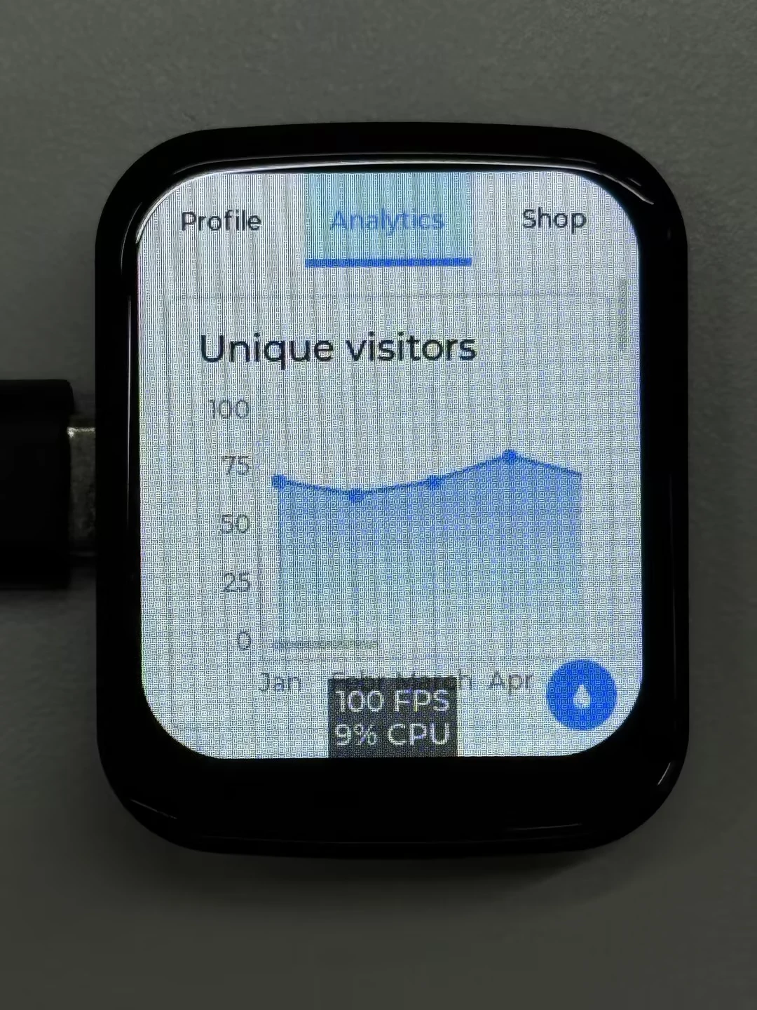 |
|---|