交互式进度条
重要提示:关于开发板的兼容性
本教程的核心逻辑适用于所有 ESP32 开发板,但所有操作步骤均以 微雪 ESP32-S3-Zero 迷你开发板 为例进行讲解。如果您使用其他型号的开发板,请根据实际情况修改相应设置。
项目介绍
这个项目展示了一个交互式进度条显示系统,通过 ESP32 读取电位器的模拟信号,并在 微雪 1.5 寸 OLED 显示屏上实时显示进度。程序提供了两种显示模式:水平进度条和半圆仪表盘,用户可以通过旋转电位器来观察进度值的变化。
硬件连接
需要使用的器件有:
- 微雪 1.5 寸 OLED 模块 * 1
- 电位器 * 1
- 面包板 * 1
- 导线
- ESP32 开发板
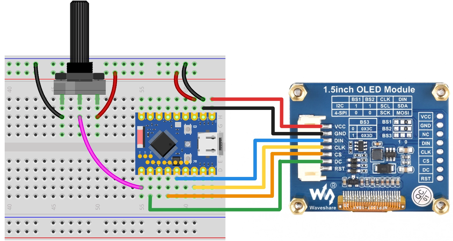
按照下面接线图连接电路:
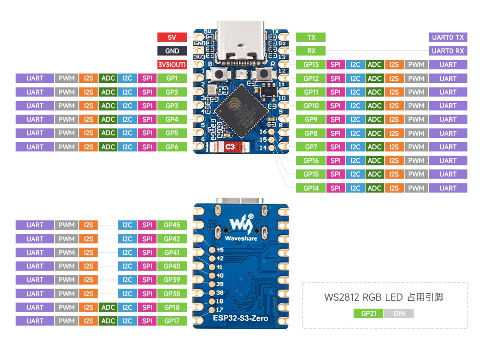
ESP32-S3-Zero 引脚图
提示
以下用 SPI 接口连接 OLED 显示屏,此屏幕也支持 I2C,通过 BS1 和 BS2 控制,如果使用 I2C 模式,请参考 第7节 I2C 通信 中的接线方式。
| ESP32 引脚 | OLED 模块 | 说明 |
|---|---|---|
| GPIO 13 | SCK | SPI 时钟线 |
| GPIO 11 | MOSI | SPI 数据输出 |
| GPIO 10 | CS | 片选信号 |
| GPIO 8 | DC | 数据/命令选择 |
| 5V | VCC | 电源正极 |
| GND | GND | 电源负极 |
代码实现
提示
此代码示例依赖 Adafruit SSD1327 库。请在 Arduino IDE 的库管理器中搜索并安装 "Adafruit SSD1327" 及其依赖项 "Adafruit GFX Library"。
/*
  交互式进度条

  此示例展示了如何在 128x128 OLED 屏幕上绘制:
  1. 水平进度条
  2. 半圆仪表盘

  - OLED SCK  -> GPIO 13
  - OLED MOSI -> GPIO 11
  - OLED CS   -> GPIO 10
  - OLED DC   -> GPIO 8
  - Potentiometer -> GPIO 7

  Wulu (Waveshare Team)
*/

#include <Adafruit_SSD1327.h>

// SPI 引脚配置
const int SCK_PIN = 13;
const int MOSI_PIN = 11;
const int CS_PIN = 10;
const int DC_PIN = 8;

// 电位器引脚
const int POT_PIN = 7;

// 创建显示器对象 (SPI)
// 128x128 分辨率
Adafruit_SSD1327 display(128, 128, &SPI, DC_PIN, -1, CS_PIN);

// 若使用 I2C,请使用以下构造函数(需确认 I2C 地址,通常为 0x3D)
// const int SDA_PIN = 2;
// const int SCL_PIN = 1;
// Adafruit_SSD1327 display(128, 128, &Wire, -1); // -1 表示无复位引脚

void setup() {
  Serial.begin(115200);

  // 初始化电位器引脚
  pinMode(POT_PIN, INPUT);

  // Wire.begin(SDA_PIN, SCL_PIN);

  // 初始化 OLED (I2C)
  // if (!display.begin(0x3D)) {
  //   Serial.println("Unable to initialize OLED");
  //   while (1) yield();
  // }

  SPI.begin(SCK_PIN, -1, MOSI_PIN, CS_PIN);

  // 初始化 OLED
  if (!display.begin()) {
    Serial.println("Unable to initialize OLED");
    while (1) yield();
  }

  display.setTextSize(1);
  display.setTextColor(SSD1327_WHITE);
  // 根据需要调整方向
  display.setRotation(0);
}

void loop() {
  // 读取数据
  int val = getPercentage();

  // 选择显示模式 (取消注释你需要的一个)

  // 模式 A: 水平进度条
  showHorizontalBar(val);

  // 模式 B: 半圆仪表盘
  // showGauge(val);

  // 简单的延时防止刷新过快
  delay(50);
}

int getPercentage() {
  // 读取电位器并返回 0-100 的整数
  // ESP32 默认 12位 (0-4095)
  int val = analogRead(POT_PIN);
  int percent = map(val, 0, 4095, 0, 100);
  return constrain(percent, 0, 100);
}

// 效果函数 1:水平进度条
void showHorizontalBar(int percent) {
  // 清除缓冲区
  display.clearDisplay();

  // 布局参数
  int barX = 10;
  int barY = 55;
  int barWidth = 108;
  int barHeight = 18;

  // 1. 绘制外框
  // SSD1327 支持灰度,但 GFX 库基础绘图通常用单色逻辑
  // 这里简单使用 WHITE
  display.drawRect(barX, barY, barWidth, barHeight, SSD1327_WHITE);

  // 2. 绘制内部填充
  // 计算填充宽度,预留 2 像素边距
  int innerMaxWidth = barWidth - 4;
  int fillWidth = (int)((percent / 100.0) * innerMaxWidth);

  if (fillWidth > 0) {
    display.fillRect(barX + 2, barY + 2, fillWidth, barHeight - 4, SSD1327_WHITE);
  }

  // 3. 绘制文字信息
  display.setCursor(32, 35);
  display.print("Progress");

  // 简单居中
  display.setCursor(50, 80);
  display.print(percent);
  display.print("%");

  // 刷新显示
  display.display();
}

// 效果函数 2:半圆仪表盘
void showGauge(int percent) {
  display.clearDisplay();

  // 仪表盘参数
  int centerX = 64;
  int centerY = 105;
  int radius = 55;
  int pointerLen = 48;

  // 1. 绘制刻度线 (模拟半圆)
  // 角度范围:180 度(左) -> 0 度(右)
  for (int i = 0; i <= 10; i++) {
    float angle = 180 - (i * 18);
    float rad = angle * PI / 180.0;

    // 外圈点
    int x1 = centerX + (int)(cos(rad) * radius);
    int y1 = centerY - (int)(sin(rad) * radius);

    // 内圈点 (刻度长度 5)
    int x2 = centerX + (int)(cos(rad) * (radius - 6));
    int y2 = centerY - (int)(sin(rad) * (radius - 6));

    display.drawLine(x1, y1, x2, y2, SSD1327_WHITE);
  }

  // 2. 绘制指针
  float currentAngle = 180 - (percent / 100.0 * 180);
  float currentRad = currentAngle * PI / 180.0;

  int needleX = centerX + (int)(cos(currentRad) * pointerLen);
  int needleY = centerY - (int)(sin(currentRad) * pointerLen);

  display.drawLine(centerX, centerY, needleX, needleY, SSD1327_WHITE);

  // 3. 绘制圆心装饰
  display.fillRect(centerX - 2, centerY - 2, 5, 5, SSD1327_WHITE);

  // 4. 文字
  display.setCursor(58, 110);
  display.print(percent);
  display.setCursor(50, 10);
  display.print("GAUGE");

  display.display();
}
代码解释
-
导入库:引入
Adafruit_SSD1327.h库,它依赖于Adafruit_GFX库来提供图形绘制功能。 -
引脚配置与初始化:
- 使用
const int定义 SPI 引脚和电位器引脚。 - 创建
Adafruit_SSD1327对象display,指定分辨率(128x128)和 SPI 控制引脚。注意这里复位引脚设置为 -1,表示未使用硬件复位引脚。 - 在
setup()中首先调用SPI.begin(...)初始化 SPI 总线,然后调用display.begin()初始化屏幕。
// 初始化 OLED (SPI)Adafruit_SSD1327 display(128, 128, &SPI, DC_PIN, -1, CS_PIN);void setup() {// ...SPI.begin(SCK_PIN, -1, MOSI_PIN, CS_PIN);if (!display.begin()) {// 初始化失败处理}// ...} - 使用
-
辅助函数
getPercentage():- 使用
analogRead(POT_PIN)读取电位器的模拟值(ESP32 默认 12 位分辨率,范围 0-4095)。 - 使用
map()函数将 0-4095 映射到 0-100。 - 使用
constrain()确保结果严格在 0-100 范围内。
- 使用
-
效果函数 1:
showHorizontalBar():display.clearDisplay():清除屏幕缓冲区。display.drawRect():绘制进度条的外框。display.fillRect():根据百分比计算宽度并绘制实心矩形作为进度条填充。display.setCursor()和display.print():设置光标位置并打印文本。display.display():将缓冲区内容发送到 OLED 显示。
-
效果函数 2:
showGauge():- 使用
cos()和sin()三角函数(需包含<math.h>,Arduino 环境默认支持)计算刻度线和指针的坐标。 display.drawLine():绘制刻度线和指针。- 逻辑与 Python 版本类似,将角度转换为弧度进行计算。
- 使用
-
主循环
loop():- 不断读取电位器值。
- 调用显示函数更新屏幕。
delay(50):添加短暂延时,避免刷新过快。