Arduino 开发
本章节包含以下部分,请按需阅读:
Arduino 入门教程
初次接触 Arduino ESP32 开发,想要快速上手?我们为您准备了一套通用的 入门教程。
- 第0节 认识 ESP32
- 第1节 安装和配置 Arduino IDE
- 第2节 Arduino 基础知识
- 第3节 数字输出/输入
- 第4节 模拟输入
- 第5节 脉冲宽度调制 (PWM)
- 第6节 串行通信 (UART)
- 第7节 I2C 通信
- 第8节 SPI 通信
- 第9节 Wi-Fi 基础用法
- 第10节 网页服务器
- 第11节 蓝牙 (Bluetooth)
- 第12节 LVGL 图形界面开发
- 第13节 综合项目
请注意:该教程使用 ESP32-S3-Zero 作为教学示例,所有硬件代码均基于其引脚布局。在动手实践前,建议您对照手中的开发板引脚图,确认引脚配置无误。
配置开发环境
1. 安装和配置 Arduino IDE
请参考 安装和配置 Arduino IDE 教程 下载安装 Arduino IDE 并添加 ESP32 支持。
| 板名称 | 板安装要求 | 版本号要求 |
|---|---|---|
| esp32 by Espressif Systems | “离线”安装/“在线”安装 | 3.2.0 |
2. 安装库
要运行示例,需要安装对应的库。
可从 此链接 下载 ESP32-C6-GEEK 开发板的示例程序包。包内的 Arduino\libraries 目录已包含本教程所需的全部库文件。
| 库或文件名称 | 说明 | 版本 | 安装方式 |
|---|---|---|---|
| ESP32-BLE-Keyboard-master | ESP32 的蓝牙键盘库 | v0.3.2 | 手动安装 |
| PubSubClient | MQTT 消息订阅发布库 | v2.8.0 | 通过库管理器或手动安装 |
| JPEGDecoder | JPEG 图像解码库 | v2.0.0 | 通过库管理器或手动安装 |
| OneButton | 单按钮事件处理库 | v2.5.0 | 通过库管理器或手动安装 |
| BME68x Sensor library | BME68x 传感器驱动库 | v1.1.40406 | 通过库管理器或手动安装 |
| ArduinoJson | 轻量 JSON 库 | v7.2.1 | 通过库管理器或手动安装 |
LVGL 及其驱动库的版本之间存在较强的依赖关系。例如,为 LVGL v8 编写的驱动可能不兼容 LVGL v9。为确保示例能够稳定复现,推荐使用上表列出的特定版本。混合使用不同版本的库可能导致编译失败或运行时异常。
安装步骤:
-
解压已下载的 示例程序包。
-
将其
Arduino\libraries目录下的所有文件夹(Arduino_DriveBus、GFX_Library_for_Arduino 等)复制到 Arduino 的库文件夹中。信息Arduino 库文件夹的路径通常是:
c:\Users\<用户名>\Documents\Arduino\libraries。也可以在 Arduino IDE 中通过 文件 > 首选项,查看“项目文件夹位置”来定位。库文件夹就是此路径下的
libraries文件夹。 -
其他安装方式请参考:Arduino 库管理教程。
ESP32-C6-GEEK 所需开发板安装说明
| 板名称 | 板安装要求 | 版本号要求 |
|---|---|---|
| ESP32 by Espressif Systems | “离线”安装/“在线”安装 | 2.0.7 |
3. 其他提示
ESP32-C6-GEEK 需要选择及配置开发板。
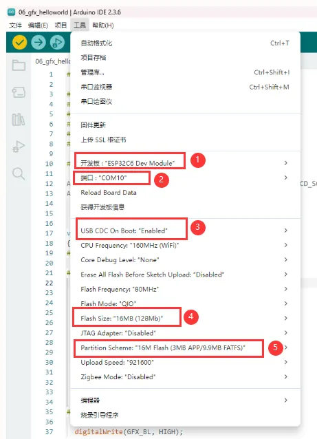
-
ESP32-C6-GEEK 需要选择 ESP32C6 Dev Module。
-
选择 USB 端口
-
ESP32-C6-GEEK 使用 ESP32-C6 原生 USB 接口,而非 UART 转 USB。对于串口通信:
-
printf()函数可直接使用; -
若要使用
Serial.println()函数,需要额外配置:在 IDE 工具菜单中启用"USB CDC On Boot"选项,或在代码中声明 HWCDC 对象处理 USB 串口通信。
-
-
选择 16MB flash
-
选择合适大小的分区表
示例程序
Arduino 示例程序位于 示例程序包 的 Arduino/examples 目录中。
| 示例程序 | 基础例程说明 | 依赖库 |
|---|---|---|
| 01_OneButton | 按钮交互与 LCD 显示 | OneButton |
| 02_ADC_Read | ADC 采样 | |
| 03_IIC_BME68X_Sensor | 驱动 I2C 模块 | BME68x Sensor libraryXPowersLib |
| 04_UART0 | 串口通信 | |
| 05_LCD_Button | 按钮操作切换图像、控制背光 | OneButton |
| 06_LCD_Time | 在 LCD 显示日期时间 | |
| 07_SD_Test | 对 SD 卡的文件进行增删改查 | |
| 08_SD_LCD | 读取 SD 卡上 JPEG 图片并在屏幕显示 | JPEGDecoder |
| 09_BLE_LCD | ESP32-C6 与 BLE 和 LCD 交互,可作为 BLE 服务器收发数据并在 LCD 显示 | ESP32-BLE-Keyboard-master |
| 10_BLE_UART | ESP32-C6 与 BLE 交互,可作为 BLE 服务器收发数据并使用 UART 显示消息内容 | ESP32-BLE-Keyboard-master |
| 11_BLE_Keyboard | 模拟 BLE 键盘 | ESP32-BLE-Keyboard-master |
| 12_WIFI_AP_LCD | 与 Wi-Fi 和 LCD 交互,可作为 Wi-Fi 接入点与客户端通信并在 LCD 显示 | |
| 13_WIFI_TCP_Client | 与 Wi-Fi 和 LCD 交互,连接 Wi-Fi 后尝试连接服务器,收发数据并在 LCD 显示 | |
| 14_WIFI_TCP_Server | 与 Wi-Fi 和 LCD 交互,作为 Wi-Fi 服务器,接收客户端数据并在 LCD 显示 | |
| 15_WIFI_Web_Server | 与 Wi-Fi 和 LCD 交互,作为 Wi-Fi 接入点服务器,处理客户端请求 | |
| 16_MQTT_sub_pub | 与 Wi-Fi 和 LCD 交互,作为 Wi-Fi 接入点服务器,处理客户端请求 | ArduinoJson,PubSubClient |
| 17_MQTT_BLE_Keyboard | 集成 BLE 键盘、Wi-Fi 和 MQTT,控制 LCD 显示 | ArduinoJson,PubSubClient,ESP32-BLE-Keyboard-master |
01_OneButton
- 该例程可使用 ESP32-C6-GEEK 的 boot 按键变成一个多功能按键,可进行单击、双击或者长按以执行不同的操作。适用于学习 ESP32-C6 的按钮交互与 LCD 显示,可通过按钮操作观察 LCD 变化,测试其可靠性
代码
01_OneButton.ino
  #include <SPI.h>
  #include "LCD_Driver.h"
  #include "GUI_Paint.h"
  #include "image.h"
  #include "OneButton.h"

  #define PIN_INPUT 9
  OneButton button(PIN_INPUT, true);

  void setup() {
    Serial.begin(115200);
    Config_Init();
    LCD_Init();
    LCD_SetBacklight(100);
    Paint_NewImage(LCD_WIDTH, LCD_HEIGHT, 90, WHITE);
    Paint_SetRotate(90);
    LCD_Clear(BLACK);
    Paint_DrawString_EN(28, 50, "Button Start", &Font24, BLACK, GREEN);

    button.attachLongPressStart(LongPressStart, &button);
    button.attachClick(Click, &button);
    button.attachDoubleClick(DoubleClick, &button);
    button.setLongPressIntervalMs(1000);
  }

  void loop() {
    // keep watching the push button:
    button.tick();
    delay(10);
  }

  // this function will be called when the button started long pressed.
  void LongPressStart(void *oneButton)
  {
    LCD_Clear(BLACK);
    Paint_DrawString_EN(50, 50, "LongPress", &Font24, BLACK, RED);
  }

  void Click(void *oneButton)
  {
    LCD_Clear(BLACK);
    Paint_DrawString_EN(75, 50, "Click", &Font24, BLACK, YELLOW);
  }

  void DoubleClick(void *oneButton)
  {
    LCD_Clear(BLACK);
    Paint_DrawString_EN(35, 50, "DoubleClick", &Font24, BLACK, BLUE);
  }
代码解释
-
按钮事件绑定:
button.attachLongPressStart(LongPressStart, &button);button.attachClick(Click, &button);button.attachDoubleClick(DoubleClick, &button);button.setLongPressIntervalMs(1000); -
持续监测 :
void loop() {// keep watching the push button:button.tick();delay(10);} -
按钮事件回调 :
void LongPressStart(void *oneButton){LCD_Clear(BLACK);Paint_DrawString_EN(50, 50, "LongPress", &Font24, BLACK, RED);}void Click(void *oneButton){LCD_Clear(BLACK);Paint_DrawString_EN(75, 50, "Click", &Font24, BLACK, YELLOW);}void DoubleClick(void *oneButton){LCD_Clear(BLACK);Paint_DrawString_EN(35, 50, "DoubleClick", &Font24, BLACK, BLUE);}
运行效果
- LCD屏幕显示

02_ADC_Read
- 该例程使用 ESP32-C6-GEEK 的 GPIO 接口,进行 ADC 采样,读取 3.3V 范围内的电压,使用时注意共地与不可超出测量范围。适用于学习 ESP32-C6 的模拟输入,可读取特定引脚模拟值,观察变化并测试稳定性
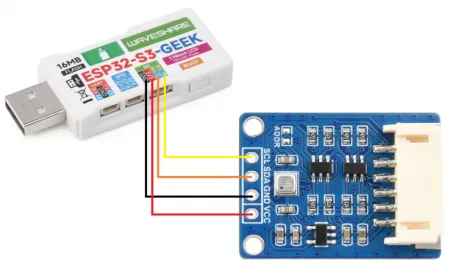
硬件连接
将 SH1.0 3PIN 杜邦线的两端分别连接到开发板和待测电压源
- 开发板 GPIO0 所连引脚用于读取所测电压
- 开发板 GND 引脚(IIC 或 UART 接口的 GND 都可以)连接到待测电压源 GND 引脚 ,确保与待测电压源的地端连接在一起
代码
02_ADC_Read.ino
#include <Arduino.h>
#define ADC1_CHANNEL_0 0 //Define the pin macro
#define DEV_BL_PIN 6
void setup() {
analogWrite(DEV_BL_PIN,0);
Serial.begin(115200); //The serial port is initially configured
analogReadResolution(12); //Set ADC resolution to 12 bits (0-4096)
}
void loop() {
//Define two variables to hold the original value and the voltage value (millivolts) collected by the ADC
int analogOriginalValue = 0;
int analogVoltsValue = 0;
analogOriginalValue = analogRead(ADC1_CHANNEL_0); // Read the ADC raw value
analogVoltsValue = analogReadMilliVolts(ADC1_CHANNEL_0); // Read ADC voltage values (millivolt range)
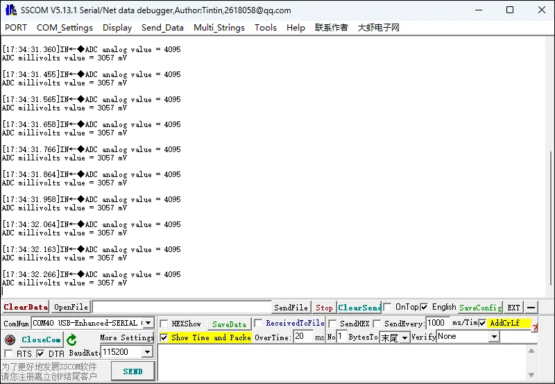
// Upload read ADC values:
Serial.printf("ADC analog value = %d\n",analogOriginalValue);
Serial.printf("ADC millivolts value = %d mV\n",analogVoltsValue);
delay(3000);
}
代码解释
-
初始化背光控制引脚为低电平
-
开启串口通信,设置波特率为 115200
-
设置 ADC 分辨率为 12 位
void setup() {analogWrite(DEV_BL_PIN,0);Serial.begin(115200); //The serial port is initially configuredanalogReadResolution(12); //Set ADC resolution to 12 bits (0-4096)} -
定义变量存储 ADC 的原始值和电压值
-
读取指定引脚的 ADC 原始值和电压值
-
通过串口输出 ADC 值
void loop() {//Define two variables to hold the original value and the voltage value (millivolts) collected by the ADCint analogOriginalValue = 0;int analogVoltsValue = 0;analogOriginalValue = analogRead(ADC1_CHANNEL_0); // Read the ADC raw valueanalogVoltsValue = analogReadMilliVolts(ADC1_CHANNEL_0); // Read ADC voltage values (millivolt range)// Upload read ADC values:Serial.printf("ADC analog value = %d\n",analogOriginalValue);Serial.printf("ADC millivolts value = %d mV\n",analogVoltsValue);delay(3000);}
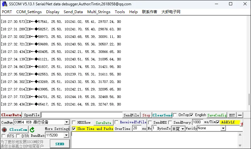
运行效果
- 打开串口调试助手
03_IIC_BME68X_Sensor
- 该例程可使用 ESP32-C6-GEEK 的 IIC 硬件接口驱动 I2C 模块,例程使用 BME680 传感器进行演示,通过串口输出打印数据。适用于学习 ESP32-C6 与 BME68X 传感器交互,可设置引脚和通信模式,读取多种数据,测试兼容性与稳定性
硬件连接
代码
03_IIC_BME68X_Sensor.ino
#include "Arduino.h"
#include "bme68xLibrary.h"
#ifndef PIN_CS
#define PIN_CS 15
#endif
#ifndef ADD_I2C
#define ADD_I2C 0x77
#endif
#ifndef PIN_SDA
#define PIN_SDA 7
#endif
#ifndef PIN_SCL
#define PIN_SCL 8
#endif
#ifndef PIN_BL
#define PIN_BL 6
#endif
Bme68x bme;
/**
* @brief Initializes the sensor and hardware settings
*/
void setup(void)
{
analogWrite(PIN_BL,0);
Wire.begin(PIN_SDA, PIN_SCL); //I2C mode
//SPI.begin(); //SPI mode
Serial.begin(115200);
delay(100);
Serial.println(PIN_SDA);
Serial.println(PIN_SCL);
while (!Serial)
delay(10);
/* initializes the sensor based on SPI library */
//bme.begin(PIN_CS, SPI); //SPI mode
bme.begin(ADD_I2C, Wire); //I2C mode
if(bme.checkStatus())
{
if (bme.checkStatus() == BME68X_ERROR)
{
Serial.println("Sensor error:" + bme.statusString());
return;
}
else if (bme.checkStatus() == BME68X_WARNING)
{
Serial.println("Sensor Warning:" + bme.statusString());
}
}
/* Set the default configuration for temperature, pressure and humidity */
bme.setTPH();
/* Set the heater configuration to 300 deg C for 100ms for Forced mode */
bme.setHeaterProf(300, 100);
Serial.println("TimeStamp(ms), Temperature(deg C), Pressure(Pa), Humidity(%), Gas resistance(ohm), Status");
}
void loop(void)
{
bme68xData data;
bme.setOpMode(BME68X_FORCED_MODE);
delay(500+bme.getMeasDur()/200);
if (bme.fetchData())
{
bme.getData(data);
Serial.print(String(millis()) + ", ");
Serial.print(String(data.temperature) + ", ");
Serial.print(String(data.pressure) + ", ");
Serial.print(String(data.humidity) + ", ");
Serial.print(String(data.gas_resistance) + ", ");
Serial.println(data.status, HEX);
}
}
代码解释
-
使用
analogWrite将背光控制引脚 PIN_BL 设置为 0,关闭背光。 -
使用
Wire.begin(PIN_SDA, PIN_SCL)初始化 I2C 通信(注释中的SPI.begin()表示也可以使用 SPI 模式,但这里未启用)。 -
初始化串口通信,设置波特率为 115200。
-
等待串口连接准备好。
-
根据配置的通信方式(这里是 I2C)初始化 BME68X 传感器。如果初始化过程中出现错误或警告,会在串口输出相应的信息。
-
设置传感器的温度、压力和湿度测量配置,并设置加热器配置。
-
在串口输出数据的标题行,包括时间戳、温度、压力、湿度、气体电阻和状态
void setup(void){analogWrite(PIN_BL,0);Wire.begin(PIN_SDA, PIN_SCL); //I2C mode//SPI.begin(); //SPI modeSerial.begin(115200);delay(100);Serial.println(PIN_SDA);Serial.println(PIN_SCL);while (!Serial)delay(10);/* initializes the sensor based on SPI library *///bme.begin(PIN_CS, SPI); //SPI modebme.begin(ADD_I2C, Wire); //I2C modeif(bme.checkStatus()){if (bme.checkStatus() == BME68X_ERROR){Serial.println("Sensor error:" + bme.statusString());return;}else if (bme.checkStatus() == BME68X_WARNING){Serial.println("Sensor Warning:" + bme.statusString());}}/* Set the default configuration for temperature, pressure and humidity */bme.setTPH();/* Set the heater configuration to 300 deg C for 100ms for Forced mode */bme.setHeaterProf(300, 100);Serial.println("TimeStamp(ms), Temperature(deg C), Pressure(Pa), Humidity(%), Gas resistance(ohm), Status");}
运行效果
- 打开串口调试助手
04_UART0
- 该例程可使用 ESP32-C6-GEEK 打开串口 UART0,打开串口调试助手,可以进行串口通信。适用于学习 ESP32-C6 串口通信,可接收数据并输出
硬件连接
代码
04_UART0.ino
#include <HardwareSerial.h>
#define DEV_BL_PIN 6
void setup() {
analogWrite(DEV_BL_PIN,0);
Serial.begin(115200);
}
void loop() {
if (Serial.available()) {
char buffer[256]; // Buffer to store input data
size_t bufferSize = 0; // Current size of data in buffer
while (Serial.available() > 0) {
char input = Serial.read();
buffer[bufferSize++] = input; // Store input in buffer
// Check if the buffer is full, or a newline character is received
if (bufferSize >= sizeof(buffer) || input == '\n') {
// Send the entire buffer via Serial2
Serial.println(buffer);
delay(10);
// Reset buffer and size for the next input
bufferSize = 0;
memset(buffer, 0, sizeof(buffer));
}
}
}
}
代码解释
-
检查串口是否有数据可读。如果有数据可读,进入循环处理输入数据。
-
创建一个字符数组
buffer用于存储输入数据,以及一个变量bufferSize用于记录缓冲区中的数据大小。 -
在循环中,每次读取一个字符并存储到缓冲区中,同时增加缓冲区大小。
-
当缓冲区已满(达到数组大小)或者读取到换行符时,将缓冲区中的数据通过串口输出,然后延迟 10 毫秒。
-
最后,重置缓冲区大小为 0,并使用
memset函数将缓冲区清零,为下一次输入做准备void loop() {if (Serial.available()) {char buffer[256]; // Buffer to store input datasize_t bufferSize = 0; // Current size of data in bufferwhile (Serial.available() > 0) {char input = Serial.read();buffer[bufferSize++] = input; // Store input in buffer// Check if the buffer is full, or a newline character is receivedif (bufferSize >= sizeof(buffer) || input == '\n') {// Send the entire buffer via Serial2Serial.println(buffer);delay(10);// Reset buffer and size for the next inputbufferSize = 0;memset(buffer, 0, sizeof(buffer));}}}}
运行效果
- 打开串口调试助手
05_LCD_Button
- 该例程可使用 ESP32-C6-GEEK 的 boot 按键实现短按点亮 LCD 并切换下一张图片,长按熄灭 LCD。适用于学习 ESP32-C6 的按钮交互和 LCD 图像显示,可通过按钮操作切换图像、控制背光,测试稳定性
代码
05_LCD_Button.ino
#include <SPI.h>
#include "LCD_Driver.h"
#include "GUI_Paint.h"
#include "image.h"
#include "OneButton.h"
#define PIN_INPUT 9
OneButton button(PIN_INPUT, true);
char click = 1;
void setup() {
Serial.begin(115200);
Config_Init();
LCD_Init();
LCD_Clear(BLACK);
LCD_SetBacklight(1000);
Paint_NewImage(LCD_WIDTH, LCD_HEIGHT, 0, BLACK);
Paint_DrawImage(gImage_pic1, 0, 0, 135, 240);
button.attachLongPressStart(LongPressStart, &button);
button.attachClick(Click, &button);
button.setLongPressIntervalMs(1000);
}
void loop() {
// keep watching the push button:
button.tick();
delay(10);
}
// this function will be called when the button started long pressed.
void LongPressStart(void *oneButton)
{
analogWrite(DEV_BL_PIN, 0);
}
  void Click(void *oneButton)
{
  LCD_SetBacklight(1000);
  Paint_NewImage(LCD_WIDTH, LCD_HEIGHT, 0, BLACK);
  click++;
  if(click >= 4)click = 1;
  switch(click)
  {
    case 1:
    Paint_DrawImage(gImage_pic1, 0, 0, 135, 240);
    break;
    case 2:
    Paint_DrawImage(gImage_pic2, 0, 0, 135, 240);
    break;
    case 3:
    Paint_DrawImage(gImage_pic3, 0, 0, 135, 240);
    break;
  }
}
代码解释
-
当按钮被点击时,此函数被调用,根据不同的
click值切换显示不同的图像(gImage_pic1、gImage_pic2、gImage_pic3):void Click(void *oneButton){LCD_SetBacklight(1000);Paint_NewImage(LCD_WIDTH, LCD_HEIGHT, 0, BLACK);click++;if(click >= 4)click = 1;switch(click){case 1:Paint_DrawImage(gImage_pic1, 0, 0, 135, 240);break;case 2:Paint_DrawImage(gImage_pic2, 0, 0, 135, 240);break;case 3:Paint_DrawImage(gImage_pic3, 0, 0, 135, 240);break;}}
运行效果
- LCD屏幕显示

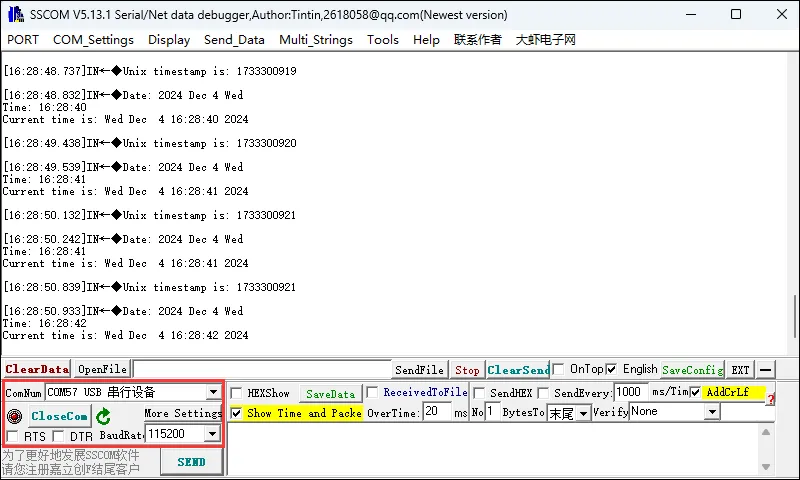
06_LCD_Time
- 该例程可使用 ESP32-C6-GEEK 连接 WIFI 获取当前时间并且把时间日期显示在 LCD 与串口调试助手上。适用于学习 ESP32-C6 的 Wi-Fi 连接与时间同步,可连接特定网络并同步时间,在 LCD 显示日期时间,测试稳定性与准确性
其余准备
- 使用 PC 打开热点,网络频带选择“任何可用频率”,将
ssid与password修改成要连接的 WIFI 名称和密码。utcOffsetInSeconds为我们需要获取时间的时区,例如:北京,东八区,则为 8 * 60 *60=28800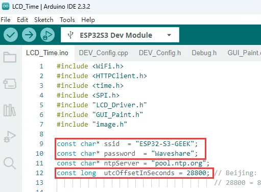
- 在此说明:ESP32-C6-GEEK 作为 STA 模式与 PC 连接同一个 WIFI 网络时,ESP32-C6-GEEK 连接的 WIFI 需要有 2.4GHz 频带的,如果没有 2.4GHz 频带,那网络频带就选择“任何可用频率”,这边我们直接选择“任何可用频率”
代码
06_LCD_Time.ino
#include <WiFi.h>
#include <HTTPClient.h>
#include <time.h>
#include <SPI.h>
#include "LCD_Driver.h"
#include "GUI_Paint.h"
#include "image.h"

const char* ssid  = "OnePlus 12";
const char* password  = "linshuchao020405";
const char* ntpServer = "pool.ntp.org";
const long  utcOffsetInSeconds = 28800; // Beijing: UTC +8 - Get the Eastern 8 Zone time (by default, the prime meridian of the Greenwich Observatory is the base line)
                                        // 28800 = 8 * 60 * 60

void setup() {
  Serial.begin(115200);

  Config_Init();
  LCD_Init();
  LCD_SetBacklight(100);
  Paint_NewImage(LCD_WIDTH, LCD_HEIGHT, 90, WHITE);
  Paint_SetRotate(90);
  LCD_Clear(BLACK);
  delay(1000);

  while (!Serial);
  Paint_DrawString_EN(20, 50, "Wifi Connecting...", &Font20, BLACK, GREEN);
  WiFi.begin(ssid, password);
  while (WiFi.status() != WL_CONNECTED) {
    delay(1000);
    Serial.println("Connecting to WiFi...");
  }
  LCD_Clear(BLACK);
  Paint_DrawString_EN(20, 50, "Wifi Connected", &Font20, BLACK, GREEN);
  Serial.println("Connected to WiFi");
  //Acquisition time
  configTime(utcOffsetInSeconds, 0, ntpServer);
  while (!time(nullptr)) {
    delay(1000);
    Serial.println("Waiting for time sync...");
  }
  LCD_Clear(BLACK);
  Serial.println("Time synced successfully");
}

void loop() {
  time_t now = time(nullptr);
  char* timeString = ctime(&now);
  removeNewlineCharacters(timeString);

  char date[20];  // Save a buffer for the date, such as "2023 Jan 01 Tue"
  char time[9];   // Save time buffer, such as "12:34:56"

  // Extract date and time
  extractDateAndTime(timeString, date, time);

  Serial.print("Date: ");
  Serial.print(date);
  Serial.print(" ");
  Serial.print((date + 6));
  Serial.print(" ");
  Serial.print((date + 10));
  Serial.print(" ");
  Serial.println((date + 14));
  Serial.print("Time: ");
  Serial.println(time);

  Serial.print("Current time is: ");
  Serial.println(timeString);  /// Print time
  Paint_DrawString_EN(55, 32, time, &Font24, BLACK, GREEN);
  Paint_DrawString_EN(15, 82, date, &Font20, BLACK, GREEN);
  Paint_DrawString_EN(80, 82, (date + 6), &Font20, BLACK, GREEN);
  Paint_DrawString_EN(135, 82, (date + 10), &Font20, BLACK, GREEN);
  Paint_DrawString_EN(175, 82, (date + 14), &Font20, BLACK, GREEN);
  // Convert current time to Unix timestamp
  long unixTimestamp = static_cast<long>(now);  //Gets a unix timestamp
  Serial.print("Unix timestamp is: ");
  Serial.println(unixTimestamp);
  delay(100);
}

void removeNewlineCharacters(char* str) {
  size_t len = strlen(str);

  // Search forward from the end of the string, dropping the ending '\r' and '\n'
  for (int i = len - 1; i >= 0; --i) {
    if (str[i] == '\r' || str[i] == '\n') {
      str[i] = '\0';  // Replace '\r' or '\n' with '\o'
    } else {
      break;          // Stop after finding the first character that is not '\r' and '\n'
    }
  }
}

void extractDateAndTime(const char* timeString, char* dateTimeStr, char* timeStr) {
  // Use the sscanf function to extract the week, month, date, and year from the string
  sscanf(timeString, "%s %s %s %s %s", dateTimeStr + 14, dateTimeStr + 6, dateTimeStr + 10, timeStr, dateTimeStr);
}
代码解释
-
在 LCD 上显示 “Wifi Connecting...”,向用户提示设备正在尝试连接 Wi-Fi,通过
WiFi.begin(ssid, password)使用指定的网络名称和密码启动连接过程,进入循环等待连接成功,在这个过程中,每隔 1000 毫秒就在串口打印 “Connecting to WiFi...”,让用户了解连接进度。一旦连接成功,就清空 LCD 屏幕并显示 “Wifi Connected”,为后续依赖网络的操作做好准备void setup() {Serial.begin(115200);Config_Init();LCD_Init();LCD_SetBacklight(100);Paint_NewImage(LCD_WIDTH, LCD_HEIGHT, 90, WHITE);Paint_SetRotate(90);LCD_Clear(BLACK);delay(1000);while (!Serial);Paint_DrawString_EN(20, 50, "Wifi Connecting...", &Font20, BLACK, GREEN);WiFi.begin(ssid, password);while (WiFi.status() != WL_CONNECTED) {delay(1000);Serial.println("Connecting to WiFi...");}LCD_Clear(BLACK);Paint_DrawString_EN(20, 50, "Wifi Connected", &Font20, BLACK, GREEN);Serial.println("Connected to WiFi");//Acquisition timeconfigTime(utcOffsetInSeconds, 0, ntpServer);while (!time(nullptr)) {delay(1000);Serial.println("Waiting for time sync...");}LCD_Clear(BLACK);Serial.println("Time synced successfully");}
运行效果
- 打开串口调试助手
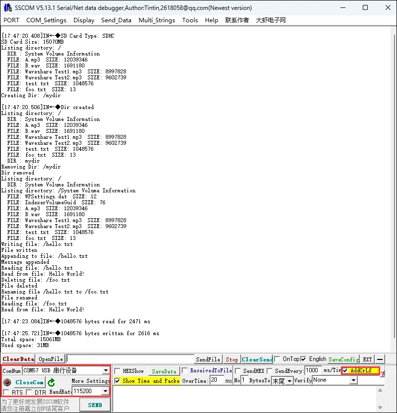
07_SD_Test
- 该例程可使用 ESP32-C6-GEEK 的 SD 卡槽,将 SD 卡插入卡槽,打开串口调试助手,可以看到 ESP32-C6-GEEK 对 SD 卡的文件进行增删改查。适用于学习 ESP32-C6 与 SD 卡交互,可进行多种文件操作,测试稳定性与可靠性
代码
07_SD_Test.ino
#include "FS.h"
#include "SD.h"
#include "SPI.h"

//Uncomment and set up if you want to use custom pins for the SPI communication
#define REASSIGN_PINS
int sck = 19;
int miso = 20;
int mosi = 18;
int cs = 23;

void listDir(fs::FS &fs, const char *dirname, uint8_t levels) {
  Serial.printf("Listing directory: %s\n", dirname);

  File root = fs.open(dirname);
  if (!root) {
    Serial.println("Failed to open directory");
    return;
  }
  if (!root.isDirectory()) {
    Serial.println("Not a directory");
    return;
  }

  File file = root.openNextFile();
  while (file) {
    if (file.isDirectory()) {
      Serial.print("  DIR : ");
      Serial.println(file.name());
      if (levels) {
        listDir(fs, file.path(), levels - 1);
      }
    } else {
      Serial.print("  FILE: ");
      Serial.print(file.name());
      Serial.print("  SIZE: ");
      Serial.println(file.size());
    }
    file = root.openNextFile();
  }
}

void createDir(fs::FS &fs, const char *path) {
  Serial.printf("Creating Dir: %s\n", path);
  if (fs.mkdir(path)) {
    Serial.println("Dir created");
  } else {
    Serial.println("mkdir failed");
  }
}

void removeDir(fs::FS &fs, const char *path) {
  Serial.printf("Removing Dir: %s\n", path);
  if (fs.rmdir(path)) {
    Serial.println("Dir removed");
  } else {
    Serial.println("rmdir failed");
  }
}

void readFile(fs::FS &fs, const char *path) {
  Serial.printf("Reading file: %s\n", path);

  File file = fs.open(path);
  if (!file) {
    Serial.println("Failed to open file for reading");
    return;
  }

  Serial.print("Read from file: ");
  while (file.available()) {
    Serial.write(file.read());
  }
  file.close();
}

void writeFile(fs::FS &fs, const char *path, const char *message) {
  Serial.printf("Writing file: %s\n", path);

  File file = fs.open(path, FILE_WRITE);
  if (!file) {
    Serial.println("Failed to open file for writing");
    return;
  }
  if (file.print(message)) {
    Serial.println("File written");
  } else {
    Serial.println("Write failed");
  }
  file.close();
}

void appendFile(fs::FS &fs, const char *path, const char *message) {
  Serial.printf("Appending to file: %s\n", path);

  File file = fs.open(path, FILE_APPEND);
  if (!file) {
    Serial.println("Failed to open file for appending");
    return;
  }
  if (file.print(message)) {
    Serial.println("Message appended");
  } else {
    Serial.println("Append failed");
  }
  file.close();
}

void renameFile(fs::FS &fs, const char *path1, const char *path2) {
  Serial.printf("Renaming file %s to %s\n", path1, path2);
  if (fs.rename(path1, path2)) {
    Serial.println("File renamed");
  } else {
    Serial.println("Rename failed");
  }
}

void deleteFile(fs::FS &fs, const char *path) {
  Serial.printf("Deleting file: %s\n", path);
  if (fs.remove(path)) {
    Serial.println("File deleted");
  } else {
    Serial.println("Delete failed");
  }
}

void testFileIO(fs::FS &fs, const char *path) {
  File file = fs.open(path);
  static uint8_t buf[512];
  size_t len = 0;
  uint32_t start = millis();
  uint32_t end = start;
  if (file) {
    len = file.size();
    size_t flen = len;
    start = millis();
    while (len) {
      size_t toRead = len;
      if (toRead > 512) {
        toRead = 512;
      }
      file.read(buf, toRead);
      len -= toRead;
    }
    end = millis() - start;
    Serial.printf("%u bytes read for %lu ms\n", flen, end);
    file.close();
  } else {
    Serial.println("Failed to open file for reading");
  }

  file = fs.open(path, FILE_WRITE);
  if (!file) {
    Serial.println("Failed to open file for writing");
    return;
  }

  size_t i;
  start = millis();
  for (i = 0; i < 2048; i++) {
    file.write(buf, 512);
  }
  end = millis() - start;
  Serial.printf("%u bytes written for %lu ms\n", 2048 * 512, end);
  file.close();
}

void setup() {
  Serial.begin(115200);
  while (!Serial) {
    delay(10);
  }

#ifdef REASSIGN_PINS
  SPI.begin(sck, miso, mosi, cs);
  if (!SD.begin(cs)) {
#else
  if (!SD.begin()) {
#endif
    Serial.println("Card Mount Failed");
    return;
  }
  uint8_t cardType = SD.cardType();

  if (cardType == CARD_NONE) {
    Serial.println("No SD card attached");
    return;
  }

  Serial.print("SD Card Type: ");
  if (cardType == CARD_MMC) {
    Serial.println("MMC");
  } else if (cardType == CARD_SD) {
    Serial.println("SDSC");
  } else if (cardType == CARD_SDHC) {
    Serial.println("SDHC");
  } else {
    Serial.println("UNKNOWN");
  }

  uint64_t cardSize = SD.cardSize() / (1024 * 1024);
  Serial.printf("SD Card Size: %lluMB\n", cardSize);

  listDir(SD, "/", 0);
  createDir(SD, "/mydir");
  listDir(SD, "/", 0);
  removeDir(SD, "/mydir");
  listDir(SD, "/", 2);
  writeFile(SD, "/hello.txt", "Hello ");
  appendFile(SD, "/hello.txt", "World!\n");
  readFile(SD, "/hello.txt");
  deleteFile(SD, "/foo.txt");
  renameFile(SD, "/hello.txt", "/foo.txt");
  readFile(SD, "/foo.txt");
  testFileIO(SD, "/test.txt");
  Serial.printf("Total space: %lluMB\n", SD.totalBytes() / (1024 * 1024));
  Serial.printf("Used space: %lluMB\n", SD.usedBytes() / (1024 * 1024));
}

void loop() {}
代码解释
-
初始化串口通信,启动 HSPI 总线并设置时钟分频,然后尝试初始化连接在特定引脚上的 SD 卡,若成功,确定 SD 卡类型并显示其容量大小。之后进行一系列对 SD 卡的文件系统操作,如列出目录、创建和删除目录、读写文件、重命名文件以及测试读写性能,同时输出 SD 卡总空间和已用空间
void setup() {Serial.begin(115200);while (!Serial) {delay(10);}#ifdef REASSIGN_PINSSPI.begin(sck, miso, mosi, cs);if (!SD.begin(cs)) {#elseif (!SD.begin()) {#endifSerial.println("Card Mount Failed");return;}uint8_t cardType = SD.cardType();if (cardType == CARD_NONE) {Serial.println("No SD card attached");return;}Serial.print("SD Card Type: ");if (cardType == CARD_MMC) {Serial.println("MMC");} else if (cardType == CARD_SD) {Serial.println("SDSC");} else if (cardType == CARD_SDHC) {Serial.println("SDHC");} else {Serial.println("UNKNOWN");}uint64_t cardSize = SD.cardSize() / (1024 * 1024);Serial.printf("SD Card Size: %lluMB\n", cardSize);listDir(SD, "/", 0);createDir(SD, "/mydir");listDir(SD, "/", 0);removeDir(SD, "/mydir");listDir(SD, "/", 2);writeFile(SD, "/hello.txt", "Hello ");appendFile(SD, "/hello.txt", "World!\n");readFile(SD, "/hello.txt");deleteFile(SD, "/foo.txt");renameFile(SD, "/hello.txt", "/foo.txt");readFile(SD, "/foo.txt");testFileIO(SD, "/test.txt");Serial.printf("Total space: %lluMB\n", SD.totalBytes() / (1024 * 1024));Serial.printf("Used space: %lluMB\n", SD.usedBytes() / (1024 * 1024));}
运行效果
- 打开串口调试助手
08_SD_LCD
- 该例程可使用 ESP32-C6-GEEK 的 SD 卡槽读取 SD 卡中的图片,将照片图片存入 SD 卡后,把 SD 卡插入卡槽,ESP32-C6-GEEK 可将 SD 卡中的照片读取并且显示在 LCD 上。适用于学习 ESP32-C6 与 SD 卡及 TFT 屏交互,可读取 SD 卡上 JPEG 图片并在屏幕显示,测试稳定性与可靠性
SD 卡准备
可将 .\ESP32-C6-GEEK-Demo\Arduino\pic 路径下的照片用读卡器存入 SD 卡中,或者存入自己的照片,将图片尺寸修改成 240×135,显示效果最佳
硬件连接
将 SH1.0 3PIN 杜邦线的两端分别连接到开发板和待测电压源
- 开发板 GPIO6 所连引脚用于读取所测电压
- 开发板 GND 引脚(IIC 或 UART 接口的 GND 都可以)连接到待测电压源 GND 引脚 ,确保与待测电压源的地端连接在一起
代码
08_SD_LCD.ino
#include <SPI.h>
#include <SD.h>
#include <JPEGDecoder.h>
#include "LCD_Driver.h"
#include "GUI_Paint.h"
#include "image.h"
#include "OneButton.h"

#define PIN_INPUT 9
#define SD_CS   23   // 片选引脚
#define SD_MOSI 18  // MOSI 引脚
#define SD_MISO 20  // MISO 引脚
#define SD_SCK  19  // SCK 引脚

OneButton button(PIN_INPUT, true);

char click = 0;
int totalImages = 0;
String imageFiles[50]; // 存储图片文件名

SPIClass sdSPI(FSPI);

void setup() {
  Serial.begin(115200);

  sdSPI.begin(SD_SCK, SD_MISO, SD_MOSI, SD_CS);

  // 初始化 SD 卡
  if (!SD.begin(SD_CS,sdSPI)) {
    Serial.println("SD 卡初始化失败!");
    //return;
  }
  else{
      Serial.println("SD 卡初始化成功");
  }

  // 扫描 SD 卡中的图片文件
  scanImageFiles();

  Config_Init();
  LCD_Init();
  LCD_Clear(BLACK);
  LCD_SetBacklight(1000);
  Paint_NewImage(LCD_WIDTH, LCD_HEIGHT, 0, BLACK);

  // 显示第一张图片(可以是内置的或 SD 卡的)
  if (totalImages > 0) {
    showSDImage(0); // 显示 SD 卡第一张图片
  } else {
    Paint_DrawImage(gImage_pic1, 0, 0, 135, 240); // 显示内置图片
  }

  button.attachLongPressStart(LongPressStart, &button);
  button.attachClick(Click, &button);
  button.setLongPressIntervalMs(1000);
}

void loop() {
  button.tick();
  delay(10);
}

void LongPressStart(void *oneButton) {
  analogWrite(DEV_BL_PIN, 0);
}

void Click(void *oneButton) {
  LCD_SetBacklight(1000);
  Paint_NewImage(LCD_WIDTH, LCD_HEIGHT, 0, BLACK);
  click++;

  if (totalImages > 0) {
    // 使用 SD 卡图片
    if (click >= totalImages) click = 0;
    showSDImage(click);
  } else {
    // 使用内置图片
    if (click >= 4) click = 1;
    switch(click) {
      case 1:
        Paint_DrawImage(gImage_pic1, 0, 0, 135, 240);
        break;
      case 2:
        Paint_DrawImage(gImage_pic2, 0, 0, 135, 240);
        break;
      case 3:
        Paint_DrawImage(gImage_pic3, 0, 0, 135, 240);
        break;
    }
  }
}

// 扫描 SD 卡中的图片文件
void scanImageFiles() {
  File root = SD.open("/");
  totalImages = 0;

  while (File file = root.openNextFile()) {
    String fileName = file.name();
    if (fileName.endsWith(".jpg") || fileName.endsWith(".jpeg") || fileName.endsWith(".JPG")) {
      imageFiles[totalImages] = fileName;
      totalImages++;
      Serial.println("找到图片:" + fileName);
      if (totalImages >= 50) break; // 最多存储 50 个文件名
    }
    file.close();
  }
  root.close();
  Serial.println("总共找到 " + String(totalImages) + " 张图片");
}

// 显示 SD 卡中的 JPEG 图片
void showSDImage(int index) {
  if (index < 0 || index >= totalImages) return;

  String filePath = "/" + imageFiles[index];
  Serial.println("显示图片:" + filePath);

  File jpegFile = SD.open(filePath, FILE_READ);
  if (!jpegFile) {
    Serial.println("无法打开文件:" + filePath);
    return;
  }

  // 解码并显示 JPEG
  boolean decoded = JpegDec.decodeSdFile(filePath.c_str());

  if (decoded) {
    // 图片信息
    Serial.print("图片尺寸:");
    Serial.print(JpegDec.width);
    Serial.print(" x ");
    Serial.print(JpegDec.height);
    Serial.print(", MCU 尺寸:");
    Serial.print(JpegDec.MCUWidth);
    Serial.print(" x ");
    Serial.println(JpegDec.MCUHeight);

    // 调整图片尺寸以适应屏幕
    renderJPEG();
  } else {
    Serial.println("JPEG 解码失败");
  }

  jpegFile.close();
}

void renderJPEG() {
  uint16_t *pImg;
  uint16_t mcu_w = JpegDec.MCUWidth;
  uint16_t mcu_h = JpegDec.MCUHeight;
  uint32_t jpeg_width = JpegDec.width;
  uint32_t jpeg_height = JpegDec.height;

  Serial.print("270 度旋转:");
  Serial.print(jpeg_width);
  Serial.print(" x ");
  Serial.println(jpeg_height);

  uint16_t rotated_width = jpeg_height;   // 135
  uint16_t rotated_height = jpeg_width;   // 240

  uint16_t x_pos = (LCD_WIDTH - rotated_width) / 2;
  uint16_t y_pos = (LCD_HEIGHT - rotated_height) / 2;

  Paint_Clear(WHITE);

  while (JpegDec.read()) {
    pImg = JpegDec.pImage;

    uint16_t mcu_x = JpegDec.MCUx * mcu_w;
    uint16_t mcu_y = JpegDec.MCUy * mcu_h;

    for (int y = 0; y < mcu_h; y++) {
      for (int x = 0; x < mcu_w; x++) {
        uint16_t orig_x = mcu_x + x;
        uint16_t orig_y = mcu_y + y;

        if (orig_x >= jpeg_width || orig_y >= jpeg_height) continue;

        // 旋转公式:
        uint16_t screen_x = x_pos + (jpeg_height - orig_y - 1);
        uint16_t screen_y = y_pos + orig_x;

        if (screen_x < LCD_WIDTH && screen_y < LCD_HEIGHT) {
          uint16_t color = pImg[x + y * mcu_w];
          Paint_SetPixel(screen_x, screen_y, color);
        }
      }
    }
  }

  JpegDec.abort();
}
代码解释
-
解码 JPEG 图片并居中绘制到 TFT 显示屏上
void renderJPEG() {uint16_t *pImg;uint16_t mcu_w = JpegDec.MCUWidth;uint16_t mcu_h = JpegDec.MCUHeight;uint32_t jpeg_width = JpegDec.width;uint32_t jpeg_height = JpegDec.height;Serial.print("270 度旋转:");Serial.print(jpeg_width);Serial.print(" x ");Serial.println(jpeg_height);uint16_t rotated_width = jpeg_height; // 135uint16_t rotated_height = jpeg_width; // 240uint16_t x_pos = (LCD_WIDTH - rotated_width) / 2;uint16_t y_pos = (LCD_HEIGHT - rotated_height) / 2;Paint_Clear(WHITE);while (JpegDec.read()) {pImg = JpegDec.pImage;uint16_t mcu_x = JpegDec.MCUx * mcu_w;uint16_t mcu_y = JpegDec.MCUy * mcu_h;for (int y = 0; y < mcu_h; y++) {for (int x = 0; x < mcu_w; x++) {uint16_t orig_x = mcu_x + x;uint16_t orig_y = mcu_y + y;if (orig_x >= jpeg_width || orig_y >= jpeg_height) continue;// 旋转公式:uint16_t screen_x = x_pos + (jpeg_height - orig_y - 1);uint16_t screen_y = y_pos + orig_x;if (screen_x < LCD_WIDTH && screen_y < LCD_HEIGHT) {uint16_t color = pImg[x + y * mcu_w];Paint_SetPixel(screen_x, screen_y, color);}}}}JpegDec.abort();}
09_BLE_LCD
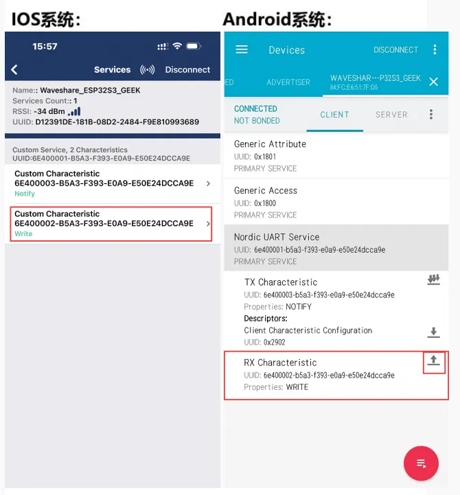
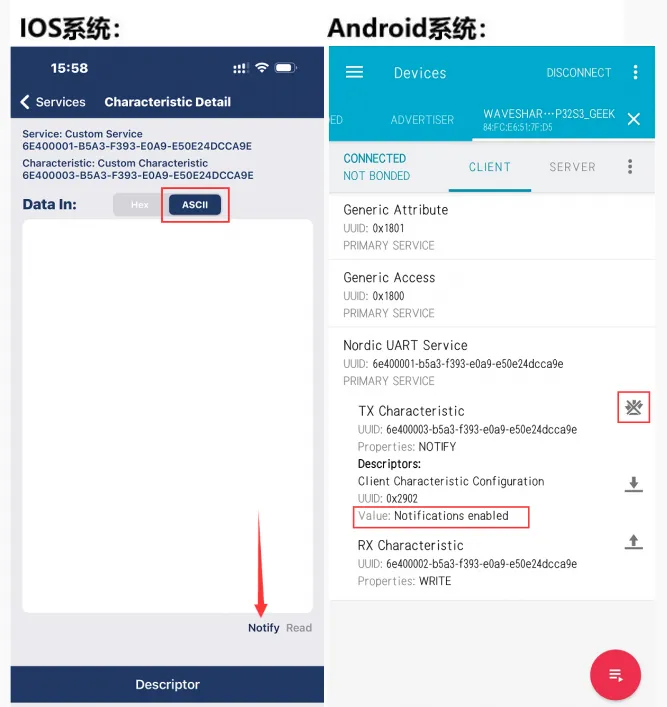
- 该例程可使用 ESP32-C6-GEEK 打开蓝牙 BLE,使用手机打开蓝牙调试助手,连接 ESP32-C6-GEEK,与手机进行蓝牙 BLE 通讯,发送与接收的消息在 LCD 上显示。适用于学习 ESP32-C6 与 BLE 和 LCD 交互,可作为 BLE 服务器收发数据并在 LCD 显示,测试稳定性与可靠性
代码
09_BLE_LCD.ino
#include <SPI.h>
#include "LCD_Driver.h"
#include "GUI_Paint.h"
#include "image.h"
#include <BLEDevice.h>
#include <BLEServer.h>
#include <BLEUtils.h>
#include <BLE2902.h>

BLEServer *pServer = NULL;
BLECharacteristic * pTxCharacteristic;
bool deviceConnected = false;
bool oldDeviceConnected = false;
uint8_t txValue = 0;

#define SERVICE_UUID           "6E400001-B5A3-F393-E0A9-E50E24DCCA9E" // UART service UUID
#define CHARACTERISTIC_UUID_RX "6E400002-B5A3-F393-E0A9-E50E24DCCA9E"
#define CHARACTERISTIC_UUID_TX "6E400003-B5A3-F393-E0A9-E50E24DCCA9E"

class MyServerCallbacks: public BLEServerCallbacks {
    void onConnect(BLEServer* pServer) {
      deviceConnected = true;
    };

    void onDisconnect(BLEServer* pServer) {
      deviceConnected = false;
    }
};

class MyCallbacks: public BLECharacteristicCallbacks {
    void onWrite(BLECharacteristic *pCharacteristic) {
      String rxValue = pCharacteristic->getValue();
      if (rxValue.length() > 0) {
        Serial.println("***************");
        Serial.print("Received Value: ");
        for (int i = 0; i < rxValue.length(); i++)
          Serial.print(rxValue[i]);
        Serial.println();
        Serial.println("***************");
        const char *rxValue1 = rxValue.c_str();
        Paint_NewImage(LCD_WIDTH, LCD_HEIGHT, 90, WHITE);
        Paint_SetRotate(90);
        LCD_Clear(BLACK);
        Paint_DrawString_EN(0, 10, "***************", &Font24, BLACK, WHITE);
        Paint_DrawString_EN(0, 35, "Receive Value:", &Font24, BLACK, WHITE);
        Paint_DrawString_EN(0, 58, rxValue1, &Font20, BLACK, 0xfff0);
        Paint_DrawString_EN(0, 100, "***************", &Font24, BLACK, WHITE);
      }
    }
};

void sendBluetoothData(uint8_t *data, size_t length) {
  if (deviceConnected) {
    pTxCharacteristic->setValue(data, length);
    pTxCharacteristic->notify();
  }
}

void setup()
{
  Config_Init();
  LCD_Init();
  Serial.begin(115200);
  LCD_Clear(BLACK);
  LCD_SetBacklight(1000);
  Paint_NewImage(LCD_WIDTH, LCD_HEIGHT, 0, BLACK);
  Paint_DrawImage(gImage_pic1, 0, 0, 135, 240);
  // Create the BLE Device
  BLEDevice::init("Waveshare_ESP32C6_GEEK");
  // Create the BLE Server
  pServer = BLEDevice::createServer();
  pServer->setCallbacks(new MyServerCallbacks());
  // Create the BLE Service
  BLEService *pService = pServer->createService(SERVICE_UUID);
  // Create a BLE Characteristic
  pTxCharacteristic = pService->createCharacteristic(
										CHARACTERISTIC_UUID_TX,
										BLECharacteristic::PROPERTY_NOTIFY
									);

  pTxCharacteristic->addDescriptor(new BLE2902());

  BLECharacteristic * pRxCharacteristic = pService->createCharacteristic(
											 CHARACTERISTIC_UUID_RX,
											BLECharacteristic::PROPERTY_WRITE
										);

  pRxCharacteristic->setCallbacks(new MyCallbacks());
  // Start the service
  pService->start();
  // Start advertising
  pServer->getAdvertising()->start();
  Serial.println("Waiting a client connection to notify...");
}

void loop()
{
  // Read all available data from Serial and send it via BLE
  if (Serial.available() > 0) {
    String readBuff;
    char readBuff1[100];
    size_t bufferSize = 0;  // Current size of data in buffer

    while (Serial.available() > 0) {
      char input = Serial.read();
      readBuff += input;  // Store input in buffer
      bufferSize ++;
      // Check if the buffer is full, or a newline character is received
      if (input == '\n') {
        // Send the entire buffer via BLE
        int idx = readBuff.lastIndexOf("\r");
        readBuff = readBuff.substring(0,idx);
        sprintf(readBuff1,"%s",readBuff);
        sendBluetoothData((uint8_t*)readBuff1, (bufferSize - 2));
        Serial.println("***************");
        Serial.print("Send Value: ");
        Serial.print(readBuff1);
        Serial.println();
        Serial.println("***************");
        Paint_NewImage(LCD_WIDTH, LCD_HEIGHT, 90, WHITE);
        Paint_SetRotate(90);
        LCD_Clear(BLACK);
        Paint_DrawString_EN(0, 10, "***************", &Font24, BLACK, WHITE);
        Paint_DrawString_EN(0, 35, "Send Value:", &Font24, BLACK, WHITE);
        Paint_DrawString_EN(0, 58, readBuff1, &Font20, BLACK, 0xfff0);
        Paint_DrawString_EN(0, 100, "***************", &Font24, BLACK, WHITE);
        // Reset buffer and size for the next input
        bufferSize = 0;
        readBuff = "";
        memset(readBuff1, 0, sizeof(readBuff1));
      }
    }
  }

  // Your other low-power operations can be added here

  delay(10);  // Introduce a short delay for power efficiency

    // disconnecting
    if (!deviceConnected && oldDeviceConnected) {
        delay(500); // give the bluetooth stack the chance to get things ready
        pServer->startAdvertising(); // restart advertising
        Serial.println("start advertising");
        oldDeviceConnected = deviceConnected;
    }
    // connecting
    if (deviceConnected && !oldDeviceConnected) {
		// do stuff here on connecting
        oldDeviceConnected = deviceConnected;
    }
}

/*********************************************************************************************************
  END FILE
*********************************************************************************************************/
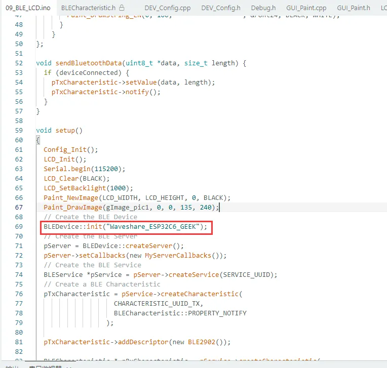
运行效果
BLEDevice::init("Waveshare_ESP32C6_GEEK") 中 Waveshare_ESP32C6_GEEK 为蓝牙名称
-
使用手机端打开手机蓝牙调试助手扫描连接设备
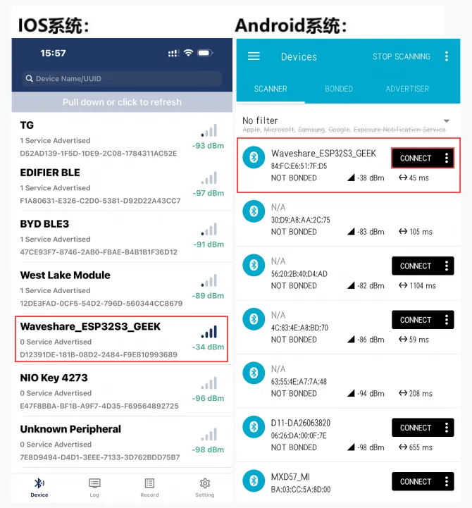
-
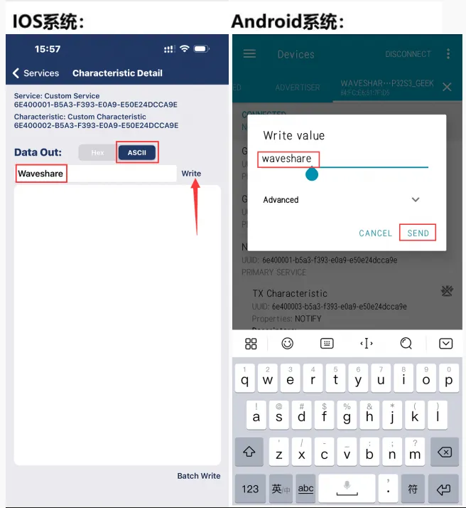
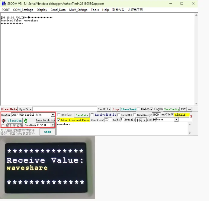
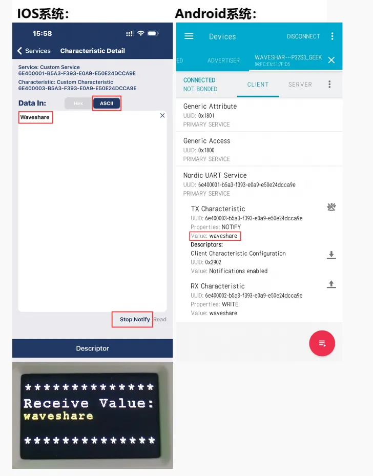
使用手机蓝牙调试助手发送蓝牙消息至 ESP32-C6-GEEK,ESP32-C6-GEEK 接收到消息会把消息显示在 LCD 上,串口调试助手打印消息内容
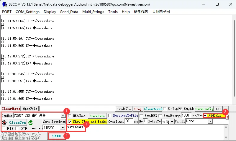
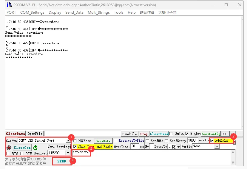
-
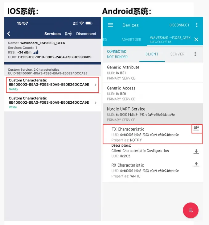
手机端的蓝牙调试助手打开接收设置,ESP32-C6-GEEK 使用 USB 转 UART 连接 PC,打开串口调试助手,发送串口消息转为蓝牙消息至手机,注意发送时要勾选上回车加换行,发送的消息内容会显示在 LCD 上,在手机端观察是否接收到蓝牙消息
10_BLE_UART
- 该例程可使用 ESP32-C6-GEEK 打开蓝牙 BLE,使用手机打开蓝牙调试助手,连接 ESP32-C6-GEEK,与手机进行蓝牙 BLE 通讯,发送与接收的消息在串口上显示。操作与 09_BLE_LCD 相同,但是没有开启 LCD,使用 UART 显示消息内容,较大程度将功耗降低。操作请看 09_BLE_LCD
11_BLE_Keyboard
- 该例程可将 ESP32-C6-GEEK 作为蓝牙键盘使用,使用 PC 蓝牙连接 ESP32-C6-GEEK,可以进行一系列键盘单键或组合操作。适用于 ESP32-C6-GEEK 模拟 BLE 键盘,可发送文本和按键指令,测试稳定性与可靠性
- 按下 boot 键重新上电便可退出程序
代码
11_BLE_Keyboard.ino
/**
 * This example turns the ESP32 into a Bluetooth LE keyboard that writes the words, presses Enter, presses a media key and then Ctrl+Alt+Delete
 */
#include <BleKeyboard.h>

BleKeyboard bleKeyboard("ESP32-C6-GEEK", "Waveshare", 100);

void setup() {
  Serial.begin(115200);
  Serial.println("Starting BLE work!");
  bleKeyboard.begin();
}

void loop() {
  if(bleKeyboard.isConnected()) {
    Serial.println("Sending 'Waveshare'...");
    bleKeyboard.print("waveshare");

    delay(500);

    Serial.println("Sending Enter key...");
    bleKeyboard.write(KEY_RETURN);

    delay(500);

    Serial.println("Sending Ctrl+Alt+Delete...");
    bleKeyboard.press(KEY_LEFT_CTRL);
    bleKeyboard.press(KEY_LEFT_ALT);
    bleKeyboard.press(KEY_DELETE);
    delay(100);
    bleKeyboard.releaseAll();
  }

  Serial.println("Waiting 5 seconds...");
  delay(5000);
}
代码解释
-
蓝牙名称
BleKeyboard bleKeyboard("ESP32-C6-GEEK", "Waveshare", 100);判断蓝牙键盘是否连接,如果连接:
- 在串口输出提示信息 “Sendin 'Waveshare'...”,然后使用
print方法发送字符串 “waceshare”。 - 在串口输出提示信息 “Sendin Enter key...”,然后使用
write方法发送回车键(KEY_RETURN)。 - 在串口输出提示信息 “Sendin Ctrl+Alt+Delete...”,依次按下左 Ctrl、左 Alt 和 Delete 键,延迟 100 毫秒后释放所有按键。
- 在串口输出提示信息 “Waiting 5 seconds...”,然后延迟 5000 毫秒,等待下一次循环
void loop() {if(bleKeyboard.isConnected()) {Serial.println("Sending 'Waveshare'...");bleKeyboard.print("waveshare");delay(500);Serial.println("Sending Enter key...");bleKeyboard.write(KEY_RETURN);delay(500);Serial.println("Sending Ctrl+Alt+Delete...");bleKeyboard.press(KEY_LEFT_CTRL);bleKeyboard.press(KEY_LEFT_ALT);bleKeyboard.press(KEY_DELETE);delay(100);bleKeyboard.releaseAll();}Serial.println("Waiting 5 seconds...");delay(5000);} - 在串口输出提示信息 “Sendin 'Waveshare'...”,然后使用
运行效果
- 使用 PC 打开蓝牙扫描连接设备
- 连接成功后会每隔 5 秒会进行一系列键盘操作(输出 “Waveshare”、Ctrl+Alt+Delete)
- 按下 boot 键重新上电便可退出程序
- 可在
libraries文件夹中的BleKeyboard.h文件中查看各个单键的值
12_WIFI_AP_LCD
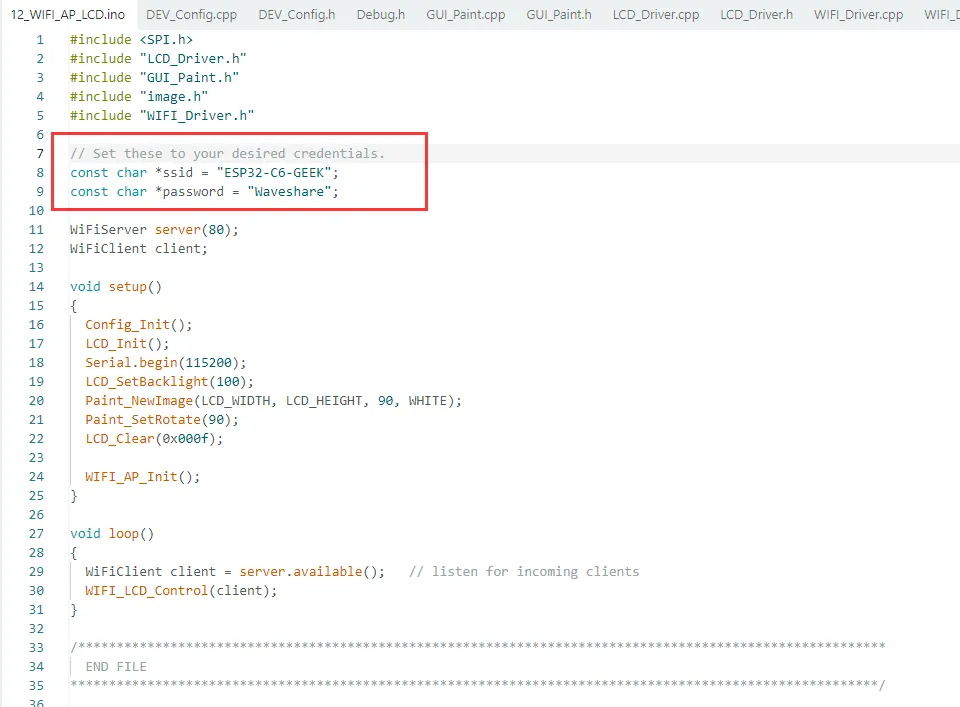
- 该例程可使用 ESP32-C6-GEEK 打开 WIFI 的 AP 模式,PC 连接其 WIFI 后,可以登录 IP,在网页端进行控制 ESP32-C6-GEEK 的 LCD 显示图片。适用于学习 ESP32-C6-GEEK 与 Wi-Fi 和 LCD 交互,可作为 Wi-Fi 接入点与客户端通信并在 LCD 显示,测试稳定性与可靠性
代码
12_WIFI_AP_LCD.ino
#include <SPI.h>
#include "LCD_Driver.h"
#include "GUI_Paint.h"
#include "image.h"
#include "WIFI_Driver.h"

// Set these to your desired credentials.
const char *ssid = "ESP32-C6-GEEK";
const char *password = "Waveshare";

WiFiServer server(80);
WiFiClient client;

void setup()
{
  Config_Init();
  LCD_Init();
  Serial.begin(115200);
  LCD_SetBacklight(100);
  Paint_NewImage(LCD_WIDTH, LCD_HEIGHT, 90, WHITE);
  Paint_SetRotate(90);
  LCD_Clear(0x000f);

  WIFI_AP_Init();
}

void loop()
{
  WiFiClient client = server.available();   // listen for incoming clients
  WIFI_LCD_Control(client);
}
代码解释
-
初始化相关配置和 LCD 显示屏
-
调用
WIFI_AP_Init()初始化 Wi-Fi 接入点void setup(){Config_Init();LCD_Init();Serial.begin(115200);LCD_SetBacklight(100);Paint_NewImage(LCD_WIDTH, LCD_HEIGHT, 90, WHITE);Paint_SetRotate(90);LCD_Clear(0x000f);WIFI_AP_Init();} -
通过
WiFiClient client = server.available();监听是否有客户端连接到服务器。 -
调用
WIFI_LCD_Control(client)函数处理连接的客户端,可能进行与 LCD 显示相关的操作,具体功能取决于该函数的实现void loop(){WiFiClient client = server.available(); // listen for incoming clientsWIFI_LCD_Control(client);}
运行效果
ssid 是 ESP32-C6-GEEK 创建的 AP 名称 (ESP32-C6-GEEK),password 则是连接 AP 的密码 (Waveshare)
-
使用 PC 连接 ESP32-C6-GEEK 的 AP,输入密码 Waveshare
-
烧录成功但 PC 识别不到 wifi 时,给开发板重新上电再尝试
-
LCD 会显示 HTTP 服务器的 IP 地址

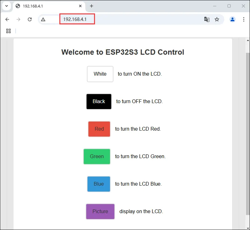
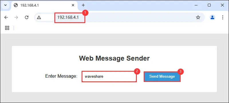
使用浏览器进行登录 IP:192.168.4.1,通过服务器上的按钮对 ESP32-C6-GEEK 的 LCD 进行控制,按下不同按钮,观察 LCD 变化,更多 LCD 的显示函数具体可以看 LCD 程序说明
13_WIFI_TCP_Client
- 该例程可使用 ESP32-C6-GEEK 打开 WIFI 的 STA 模式,与 PC 端或者手机端连接同一个 WIFI 后,作为 TCP Client 访问 PC 或手机创建的 TCP Server,并且与 PC 或手机建立 TCP 通讯,在 LCD 上显示接收内容。适用于学习 ESP32-C6-GEEK 与 Wi-Fi 和 LCD 交互,连接 Wi-Fi 后尝试连接服务器,收发数据并在 LCD 显示,测试稳定性与可靠性
代码修改
-
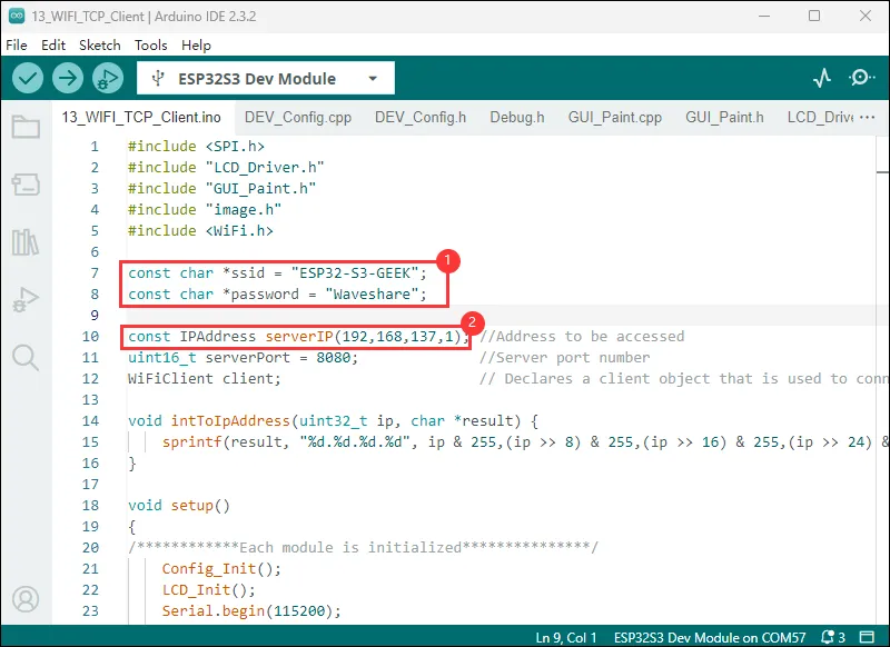
使用 PC 打开热点,网络频带选择“任何可用频率”,程序中 ssid 与 password 与要连接的 WIFI 名称和密码保持一致
-
下载 网络调试助手,修改为你的本地 IP 地址(以下的 192.168.137.1 为示例 IP 地址)
代码
13_WIFI_TCP_Client.ino
#include <SPI.h>
#include "LCD_Driver.h"
#include "GUI_Paint.h"
#include "image.h"
#include <WiFi.h>
const char *ssid = "WSTEST";
const char *password = "waveshare0755";
const IPAddress serverIP(192,168,137,7); //Address to be accessed
uint16_t serverPort = 8080; //Server port number
WiFiClient client; // Declares a client object that is used to connect to the server
void intToIpAddress(uint32_t ip, char *result) {
sprintf(result, "%d.%d.%d.%d", ip & 255,(ip >> 8) & 255,(ip >> 16) & 255,(ip >> 24) & 255);
}
void setup()
{
/************Each module is initialized***************/
Config_Init();
LCD_Init();
Serial.begin(115200);
LCD_SetBacklight(100);
Paint_NewImage(LCD_WIDTH, LCD_HEIGHT, 90, WHITE);
Paint_SetRotate(90);
LCD_Clear(0x000f);
WiFi.mode(WIFI_STA);
WiFi.setSleep(false); //Turn off wifi hibernation in STA mode to improve response speed
WiFi.begin(ssid, password);
/**************Wait for WIFI connection***************/
char point;
char line = 60;
while (WiFi.status() != WL_CONNECTED)
{
Paint_DrawString_EN(0, 5, "ESP32-C6-GEEK", &Font24, 0x000f, 0xfff0);
Paint_DrawString_EN(0, 40, "Trying to connect", &Font20, 0x000f, 0xfff0);
Paint_DrawString_EN(point, line, ".", &Font20, 0x000f, 0xfff0);
point += 8;
if(point >= 230)
{
line += 15;
point = 0;
}
printf(".\r\n");
delay(500);
}
/******************WIFI is connected******************/
LCD_Clear(0x000f);
IPAddress myIP = WiFi.localIP();
uint32_t ipAddress = WiFi.localIP();
char ipAddressStr[16];
intToIpAddress(ipAddress, ipAddressStr);
Paint_DrawString_EN(0, 20, "Connected", &Font24, 0x000f, 0xfff0);
Paint_DrawString_EN(0, 50, "MyIP:", &Font24, 0x000f, 0xfff0);
Paint_DrawString_EN(80, 54, ipAddressStr, &Font16, 0x000f, 0xfff0);
printf("Connected\r\n");
printf("IP Address:");
printf("%s\r\n", ipAddressStr);
}
void loop()
{
/***************Wait to connect server***************/
Paint_DrawString_EN(0, 83, "Trying to access", &Font20, 0x000f, 0xfff0);
printf("Trying to access the server\r\n");
/************Server connection successful************/
if (client.connect(serverIP, serverPort)) //Attempting to access the target address
{
LCD_Clear(0x000f);
Paint_DrawString_EN(0, 25, "ESP32-C6-GEEK", &Font24, 0x000f, 0xfff0);
Paint_DrawString_EN(0, 65, "Access successful", &Font20, 0x000f, 0xfff0);
printf("Access successful\r\n");
client.print("Hello world!"); //Send data to the server
/**************Receiving server message**************/
while (client.connected() || client.available()) //If it is connected or has received unread data
{
if (client.available()) //If there is data to read
{
String line = client.readStringUntil('\r'); /// Reads data to a newline
printf("Read the data:\r\n");
printf("%s\r\n",line);
client.write(line.c_str()); //Send back the received data
LCD_Clear(0x000f);
Paint_DrawString_EN(0, 10, "Received:", &Font24, 0x000f, 0xfff0);
Paint_DrawString_EN(0, 33, line.c_str(), &Font20, 0x000f, 0xff00);
}
}
printf("Close current connection\r\n");
client.stop(); //Close the client
}
else
{
printf("Access failure\r\n");
client.stop(); //Close the client
}
delay(5000);
}
/*********************************************************************************************************
END FILE
*********************************************************************************************************/
代码解释
-
使用
sprintf函数将传入的 IP 地址整数按照点分十进制的格式转换为字符串,并存储在result指针指向的字符数组中void intToIpAddress(uint32_t ip, char *result) {sprintf(result, "%d.%d.%d.%d", ip & 255,(ip >> 8) & 255,(ip >> 16) & 255,(ip >> 24) & 255);}
运行效果
-
此时 LCD 屏幕显示尝试连接,片刻之后显示已连接
-
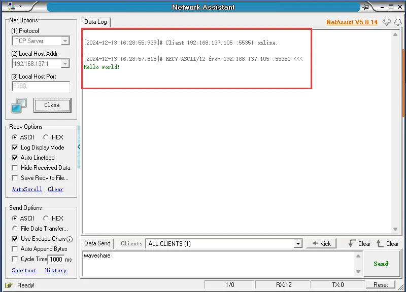
修改
NetAssist参数,协议类型为 TCP Server,本地 IP 地址与程序中保持一致,本地端口号为 8080,点击“连接”,用于和 ESP32-C6-GEEK(TCP Client) 进行连接与 TCP 通讯
-
连接成功后,TCP Server 会收到 ESP32-C6-GEEK 发送的 TCP 消息"Hello world",LCD 会显示“Access successful”
-
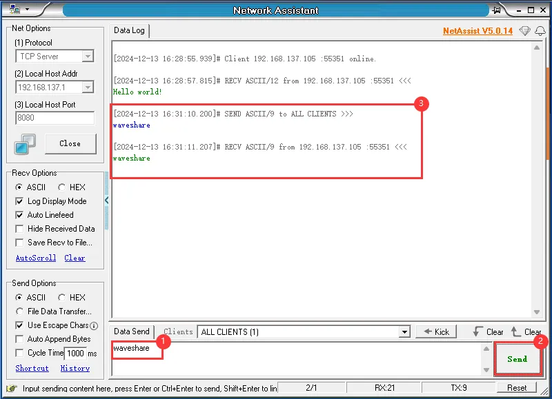
通过 PC 端 TCP Server 发送 TCP 消息给 ESP32-C6-GEEK,若发送成功,ESP32-C6-GEEK 作为 TCP Client 接收到消息会将消息内容显示在 LCD 上,可以观察到 LCD 显示消息
-
还可以使用手机打开热点,热点名称与密码同上,选择 2.4GHz 频带
-
打开热点后使用 TCP 调试助手与 ESP32-C6-GEEK 进行 TCP 通讯
-
烧录代码,连接成功后,TCP Server 会收到 ESP32-C6-GEEK 发送的 TCP 消息"Hello world",LCD 会显示“Access successful”,可通过手机端 TCP Server 发送 TCP 消息给 ESP32-C6-GEEK,若发送成功,ESP32-C6-GEEK 作为 TCP Client 接收到消息会将消息内容显示在 LCD 上,可以观察到 LCD 显示消息
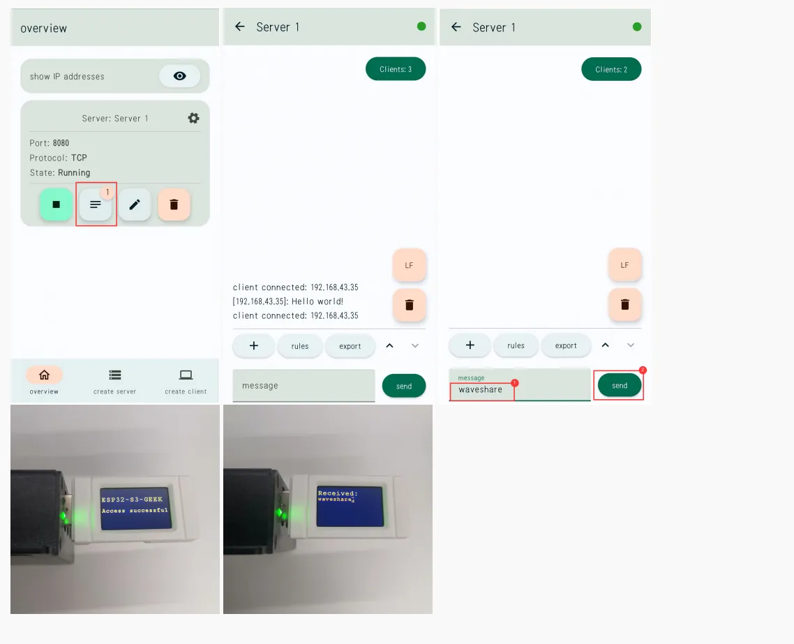
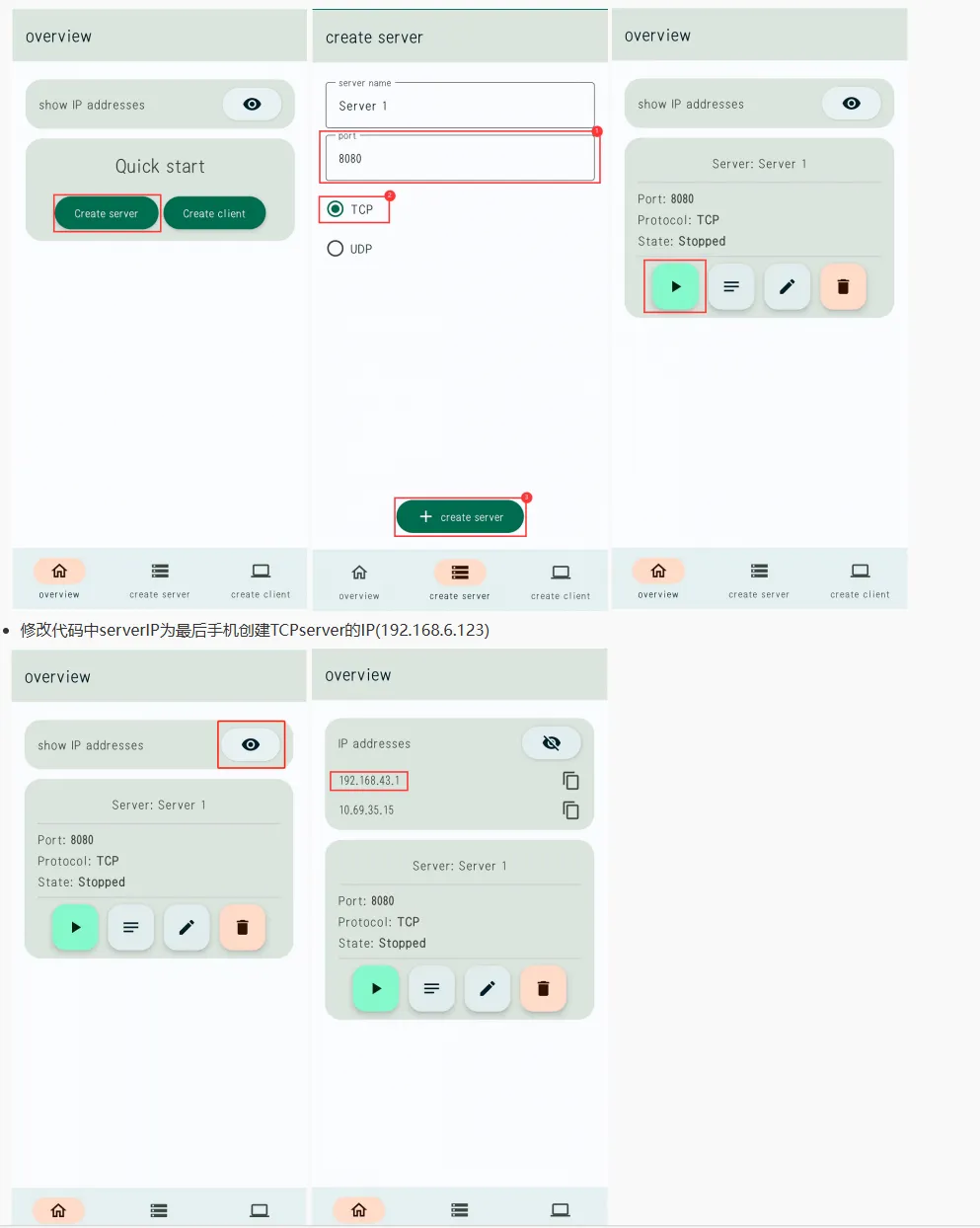
14_WIFI_TCP_Server
- 该例程可使用 ESP32-C6-GEEK 打开 WIFI 的 STA 模式,连接 PC 端打开的热点后,创建 TCP Server,PC 创建 TCP Client 访问 ESP32-C6-GEEK,两者建立 TCP 通讯,GEEK 在 LCD 上显示接收内容。适用于学习 ESP32-C6-GEEK 与 Wi-Fi 和 LCD 交互,作为 Wi-Fi 服务器,接收客户端数据并在 LCD 显示,测试稳定性与可靠性
代码修改
- 使用 PC 打开热点,网络频带选择“任何可用频率”,程序中 ssid 与 password 与要连接的 WIFI 名称和密码保持一致
代码
14_WIFI_TCP_Server.ino
#include <SPI.h>
#include "LCD_Driver.h"
#include "GUI_Paint.h"
#include "image.h"
#include <WiFi.h>
const char *ssid = "WSTEST";
const char *password = "waveshare0755";
WiFiServer server; /// Declares the server object
void intToIpAddress(uint32_t ip, char *result) {
sprintf(result, "%d.%d.%d.%d", ip & 255,(ip >> 8) & 255,(ip >> 16) & 255,(ip >> 24) & 255);
}
void setup()
{
/************Each module is initialized***************/
Config_Init();
LCD_Init();
Serial.begin(115200);
LCD_SetBacklight(100);
Paint_NewImage(LCD_WIDTH, LCD_HEIGHT, 90, 0x000f);
Paint_SetRotate(90);
LCD_Clear(0x000f);
WiFi.mode(WIFI_STA);
WiFi.setSleep(false); //Turn off wifi hibernation in STA mode to improve response speed
WiFi.begin(ssid, password);
/**************Wait for WIFI connection***************/
char point;
char line = 60;
while (WiFi.status() != WL_CONNECTED)
{
Paint_DrawString_EN(0, 5, "ESP32-C6-GEEK", &Font24, 0x000f, 0xfff0);
Paint_DrawString_EN(0, 40, "Trying to connect", &Font20, 0x000f, 0xfff0);
Paint_DrawString_EN(point, line, ".", &Font20, 0x000f, 0xfff0);
point += 12;
if(point >= 228)
{
line += 15;
point = 0;
}
printf(".\r\n");
delay(1000);
}
LCD_Clear(0x000f);
}
void loop()
{
/******************WIFI is connected******************/
IPAddress myIP = WiFi.localIP();
uint32_t ipAddress = WiFi.localIP();
char ipAddressStr[16];
intToIpAddress(ipAddress, ipAddressStr);
printf("Connected\r\n");
printf("IP Address:");
printf("%s\r\n", ipAddressStr);
server.begin(8080);
/***********Wait for the client to connect***********/
WiFiClient client = server.available(); //Try to create a customer object
Paint_DrawString_EN(0, 7, "Connected WIFI", &Font24, 0x000f, 0xfff0);
Paint_DrawString_EN(0, 50, "IP:", &Font24, 0x000f, 0xfff0);
Paint_DrawString_EN(55, 54, ipAddressStr, &Font16, 0x000f, 0xfff0);
Paint_DrawString_EN(0, 90, "Trying to access", &Font20, 0x000f, 0xfff0);
printf("Trying to access the server\r\n");
/************client connection successful************/
if (client) //If current customer available
{
printf("[Client connected]\r\n");
while (client.connected() || client.available()) //If it is connected or has received unread data
{
if (client.available()) //If there is data to read
{
String line = client.readStringUntil('\n'); // Read data from the client up to the newline character
const char* charArray = line.c_str(); // Gets a string ending in '\n'
// Removes the trailing return newline character
int length = line.length();
while (length > 0 && (line[length - 1] == '\r' || line[length - 1] == '\n')) {
length--;
}
// Creates a new array of characters, excluding the return newline character
char* modifiedCharArray = new char[length + 1];
memcpy(modifiedCharArray, charArray, length);
modifiedCharArray[length] = '\0'; // Add a null character to ensure that the character array ends in null
LCD_Clear(0x000f);
Paint_DrawString_EN(0, 10, "Received:", &Font24, 0x000f, 0xfff0);
Paint_DrawString_EN(0, 33, modifiedCharArray, &Font20, 0x000f, 0xff00);
}
}
client.stop(); //End the current connection
printf("[Client disconnected]\r\n");
}
}
/*********************************************************************************************************
END FILE
*********************************************************************************************************/
代码解释
-
使用
sprintf函数将传入的 IP 地址整数按照点分十进制的格式转换为字符串,并存储在result指针指向的字符数组中void intToIpAddress(uint32_t ip, char *result) {sprintf(result, "%d.%d.%d.%d", ip & 255,(ip >> 8) & 255,(ip >> 16) & 255,(ip >> 24) & 255);}
运行效果
- 烧录成功,LCD 显示

- Wi-Fi 连接后,LCD 上会显示 TCP ServerIP,使用串口调试助手打开 TCP Client,用于和 ESP32-C6-GEEK(TCP Server) 进行连接与 TCP 通讯
- ①. 修改端口号为"TCPClient" ,修改远程地址为 LCD 屏幕上显示的 IP,端口号 8080,点击连接
- ②. 加回车换行
- ③. 输入信息
- ①. 发送信息
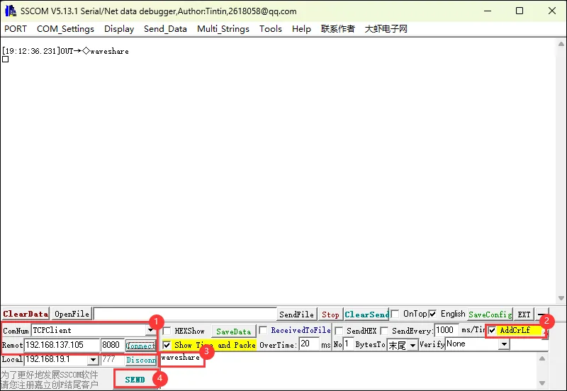
- 消息成功发送,LCD 屏幕显示

15_WIFI_Web_Server
- 该例程可使用 ESP32-C6-GEEK 打开 WIFI 的 AP 模式,PC 端连接其 WIFI 后,打开串口调试助手,通过 ESP32-C6-GEEK 创建的 HTTP 网页端发送消息给 GEEK,观察串口调试助手与 LCD 上的接收内容。适用于学习 ESP32-C6-GEEK 与 Wi-Fi 和 LCD 交互,作为 Wi-Fi 接入点服务器,处理客户端请求,测试稳定性与可靠性
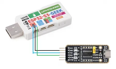
硬件连接
-
使用 ESP32-C6-GEEK 的 UART 接口通过 USB 转 UART 工具与 PC 连接,打开串口调试助手
代码
15_WIFI_Web_Server.ino
#include <SPI.h>
#include "LCD_Driver.h"
#include "GUI_Paint.h"
#include "image.h"
#include "WIFI_Driver.h"
// Set these to your desired credentials.
const char *ssid = "ESP32-C6-GEEK";
const char *password = "Waveshare";
WiFiServer server(80);
WiFiClient client;
  void setup()
{
  Config_Init();
  LCD_Init();
  Serial.begin(115200);
  LCD_SetBacklight(100);
  Paint_NewImage(LCD_WIDTH, LCD_HEIGHT, 90, WHITE);
  Paint_SetRotate(90);
  LCD_Clear(0x000f);

  WIFI_AP_Init();
}
void loop()
{
WiFiClient client = server.available(); // listen for incoming clients
WIFI_Web_Server(client);
}
代码解释
-
初始化相关配置和 LCD 显示屏
-
调用
WIFI_AP_Init()初始化 Wi-Fi 接入点void setup(){Config_Init();LCD_Init();Serial.begin(115200);LCD_SetBacklight(100);Paint_NewImage(LCD_WIDTH, LCD_HEIGHT, 90, WHITE);Paint_SetRotate(90);LCD_Clear(0x000f);WIFI_AP_Init();}
运行效果
-
烧录成功,使用 PC 连接 ESP32-C6-GEEK 的 AP
-
LCD 会显示 HTTP 服务器的 IP 地址,使用浏览器进行登录 IP:192.168.4.1
-
使用 ESP32-C6-GEEK 的 UART 接口通过 USB 转 UART 工具与 PC 连接,打开串口调试助手
-
可在 HTTP Web 上输入文本内容并且发送 HTTP 请求至 ESP32-C6-GEEK,可在串口调试助手与 LCD 上显示接收内容
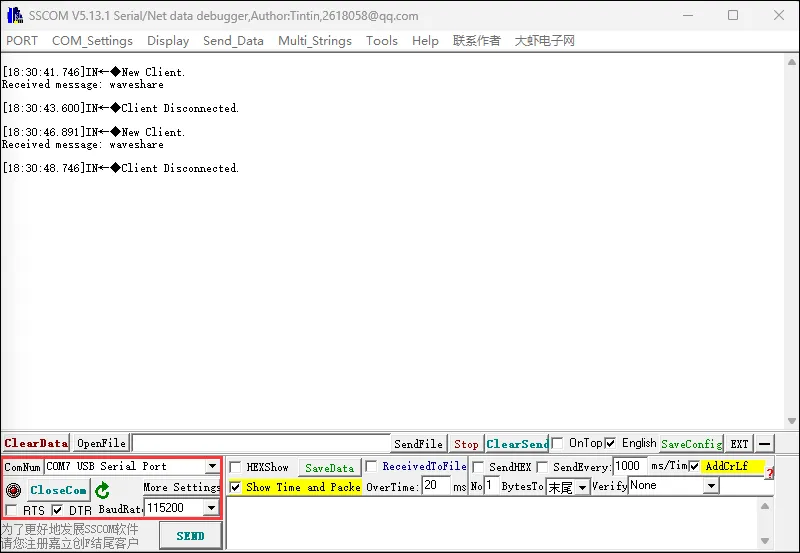

16_MQTT_sub_pub
- 该例程可使用 ESP32-C6-GEEK 打开 WIFI 的 STA 模式,连接 WIFI 后,使用微雪云平台,进行 MQTT 通讯,订阅与发布主题,实现远距离传输信息。适用于学习 ESP32-C6-GEEK 与 Wi-Fi、MQTT 和 LCD 交互,连接 Wi-Fi 和 MQTT 服务器,收发 JSON 数据并在 LCD 显示,测试稳定性与可靠性
代码
16_MQTT_sub_pub.ino
#include <ArduinoJson.h>
#include <Arduino.h>
#include <PubSubClient.h>
#include <WiFi.h>
#include <WiFiClientSecure.h>
#include <SPI.h>
#include "LCD_Driver.h"
#include "GUI_Paint.h"
#include "image.h"
#define MSG_BUFFER_SIZE (50)
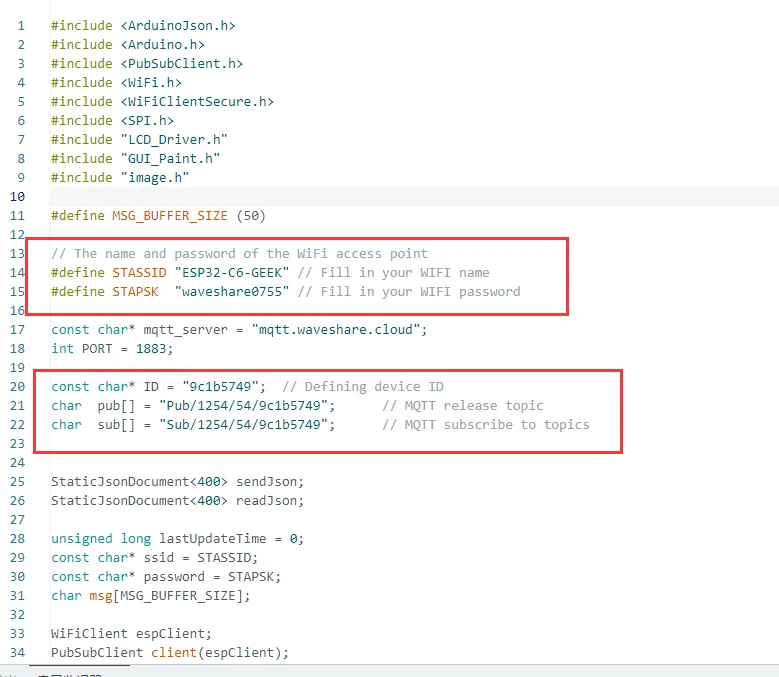
// The name and password of the WiFi access point
#define STASSID "WSTEST" // Fill in your WIFI name
#define STAPSK "waveshare0755" // Fill in your WIFI password
const char* mqtt_server = "mqtt.waveshare.cloud";
int PORT = 1883;
const char* ID = "9c1b5749"; // Defining device ID
char pub[] = "Pub/1254/54/9c1b5749"; // MQTT release topic
char sub[] = "Sub/1254/54/9c1b5749"; // MQTT subscribe to topics
StaticJsonDocument<400> sendJson;
StaticJsonDocument<400> readJson;
unsigned long lastUpdateTime = 0;
const char* ssid = STASSID;
const char* password = STAPSK;
char msg[MSG_BUFFER_SIZE];
WiFiClient espClient;
PubSubClient client(espClient);
const unsigned long updateInterval = 5000;
void setup() {
Serial.begin(115200);
Config_Init();
LCD_Init();
LCD_SetBacklight(100);
Paint_NewImage(LCD_WIDTH, LCD_HEIGHT, 90, WHITE);
Paint_SetRotate(90);
LCD_Clear(BLACK);
setup_wifi();
client.setServer(mqtt_server, PORT);
client.setCallback(callback);
}
void loop() {
if (!client.connected()) {
reconnect();
}
client.loop();
if (millis() - lastUpdateTime > updateInterval) { // Periodic data reporting
sendJsonData();
lastUpdateTime = millis();
}
}
// MQTT subscribes to callback functions for processing received messages
void callback(char* topic, byte* payload, unsigned int length) {
String inputString;
for (int i = 0; i < length; i++) {
inputString += (char)payload[i];
}
Serial.println(inputString);
int dataBegin = inputString.indexOf("\"data\"");
if (dataBegin == -1) {
Serial.println(F("Missing 'data' field in JSON."));
return;
}
int builtInBegin = inputString.indexOf("\"key\"", dataBegin); // Please change to your data identifier
if (builtInBegin == -1) {
Serial.println(F("Missing 'builtIn' field in 'data' object."));
return;
}
int valueBegin = inputString.indexOf(':', builtInBegin);
int valueEnd = inputString.indexOf('}', valueBegin);
if (valueBegin == -1 || valueEnd == -1) {
Serial.println(F("Invalid 'builtIn' value."));
return;
}
String builtInValueStr = inputString.substring(valueBegin + 1, valueEnd);
int builtInValue = builtInValueStr.toInt();
if (builtInValue == 0) {
LCD_Clear(BLACK);
Paint_DrawString_EN(75, 55, "close!", &Font24, BLACK, GREEN);
Serial.println("close!");
} else {
LCD_Clear(BLACK);
Paint_DrawString_EN(75, 55, "open!", &Font24, BLACK, GREEN);
Serial.println("open!");
}
}
void setup_wifi() {
Paint_DrawString_EN(20, 50, "Wifi Connecting...", &Font20, BLACK, GREEN);
Serial.println();
Serial.print("Connecting to ");
Serial.println(ssid);
WiFi.mode(WIFI_STA);
WiFi.begin(ssid, password);
while (WiFi.status() != WL_CONNECTED) {
delay(500);
Serial.print(".");
}
LCD_Clear(BLACK);
Paint_DrawString_EN(20, 50, "Wifi Connected", &Font20, BLACK, GREEN);
Serial.println("IP address: ");
Serial.println(WiFi.localIP());
}
// Reconnect to the MQTT server
void reconnect() {
LCD_Clear(BLACK);
Paint_DrawString_EN(20, 50, "MQTT Connecting...", &Font20, BLACK, GREEN);
while (!client.connected()) {
Serial.print("Attempting MQTT connection...");
if (client.connect(ID)) {
Serial.println("connected");
// Subscribe to the topic when the connection is successful
client.subscribe(sub);
} else {
Serial.print("failed, rc=");
Serial.print(client.state());
Serial.println(" try again in 5 seconds");
delay(5000);
}
}
LCD_Clear(BLACK);
Paint_DrawString_EN(20, 50, "MQTT Connected", &Font20, BLACK, GREEN);
}
// Send data in JSON format to MQTT server
void sendJsonData() {
sendJson["ID"] = ID;
String pubres;
serializeJson(sendJson, pubres);
int str_len = pubres.length() + 1;
char char_array[str_len];
pubres.toCharArray(char_array, str_len);
client.publish(pub, char_array);
}
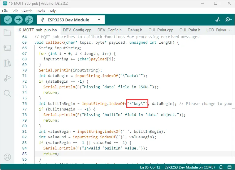
代码解释
-
将接收到的字节数组转换为字符串
inputString。 -
在字符串中查找特定的 JSON 字段,如
"data"和"key"(可根据实际情况修改为特定的数据标识符)。 -
提取出
"builtIn"字段的值,并根据该值进行不同的操作。如果值为 0,则在 LCD 上显示 “close!”,否则显示 “open!”,同时在串口输出相应信息void callback(char* topic, byte* payload, unsigned int length) {String inputString;for (int i = 0; i < length; i++) {inputString += (char)payload[i];}Serial.println(inputString);int dataBegin = inputString.indexOf("\"data\"");if (dataBegin == -1) {Serial.println(F("Missing 'data' field in JSON."));return;}int builtInBegin = inputString.indexOf("\"key\"", dataBegin); // Please change to your data identifierif (builtInBegin == -1) {Serial.println(F("Missing 'builtIn' field in 'data' object."));return;}int valueBegin = inputString.indexOf(':', builtInBegin);int valueEnd = inputString.indexOf('}', valueBegin);if (valueBegin == -1 || valueEnd == -1) {Serial.println(F("Invalid 'builtIn' value."));return;}String builtInValueStr = inputString.substring(valueBegin + 1, valueEnd);int builtInValue = builtInValueStr.toInt();if (builtInValue == 0) {LCD_Clear(BLACK);Paint_DrawString_EN(75, 55, "close!", &Font24, BLACK, GREEN);Serial.println("close!");} else {LCD_Clear(BLACK);Paint_DrawString_EN(75, 55, "open!", &Font24, BLACK, GREEN);Serial.println("open!");}} -
在 LCD 上显示 “Wifi Connecting...”。
-
在串口输出正在连接的 Wi-Fi 网络名称。
-
连接成功后,清空 LCD 屏幕并显示 “Wifi Connected”,同时在串口输出本地 IP 地址
void setup_wifi() {Paint_DrawString_EN(20, 50, "Wifi Connecting...", &Font20, BLACK, GREEN);Serial.println();Serial.print("Connecting to ");Serial.println(ssid);WiFi.mode(WIFI_STA);WiFi.begin(ssid, password);while (WiFi.status() != WL_CONNECTED) {delay(500);Serial.print(".");}LCD_Clear(BLACK);Paint_DrawString_EN(20, 50, "Wifi Connected", &Font20, BLACK, GREEN);Serial.println("IP address: ");Serial.println(WiFi.localIP());}
代码修改
开启的热点名称与密码要与代码中一致
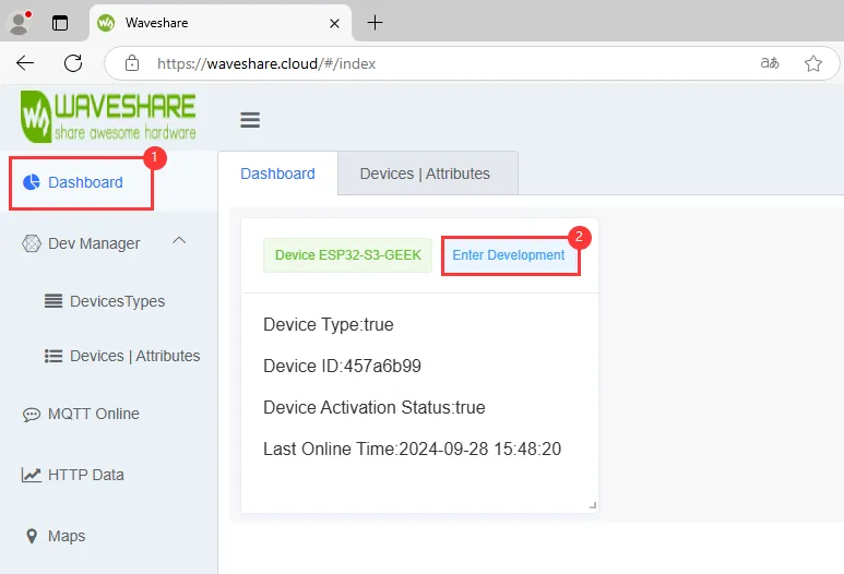
微雪云平台 账号注册与创建设备后,根据微雪云上新建设备的"查看地址"可以看到设备的 Client ID、Pub Topic、Sub Topic,将它们写入例程中进行赋值,用于 ESP32-C6-GEEK 连接自己的云平台设备
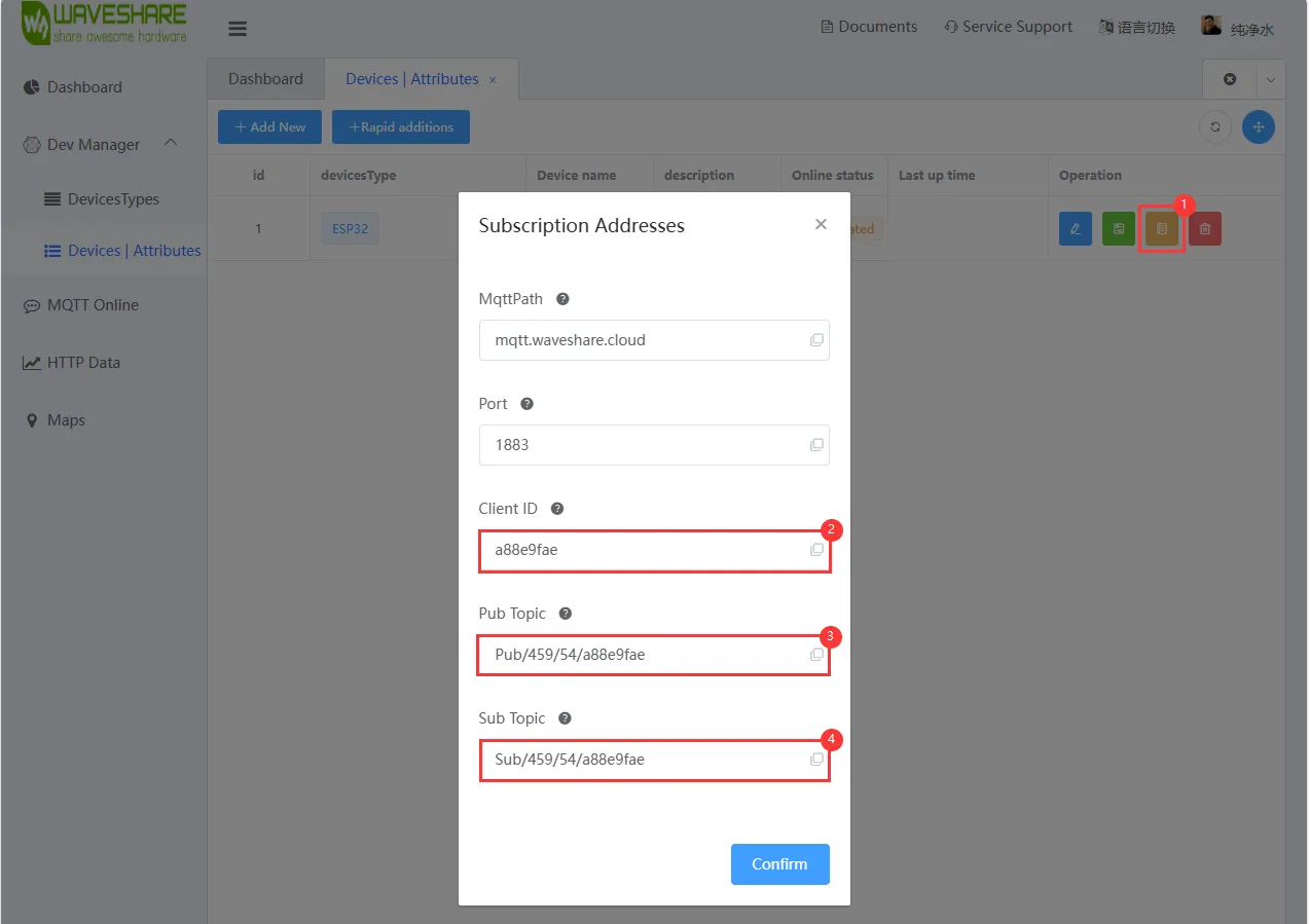
在 callback 函数中可以修改识别的标识符为我们自己在云平台上创建的设备属性标识符

运行效果
-
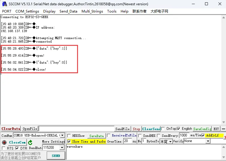
烧录代码,连接上 WIFI 后,观察微雪云平台上设备是否进入 online 状态,若没有可以尝试刷新网页与使用 USB 转 UART 连接 PC 通过串口调试助手查看 WIFI 与 MQTT 连接情况,并且在 LCD 屏上也会显示 WIFI 与 MQTT 的连接情况


-
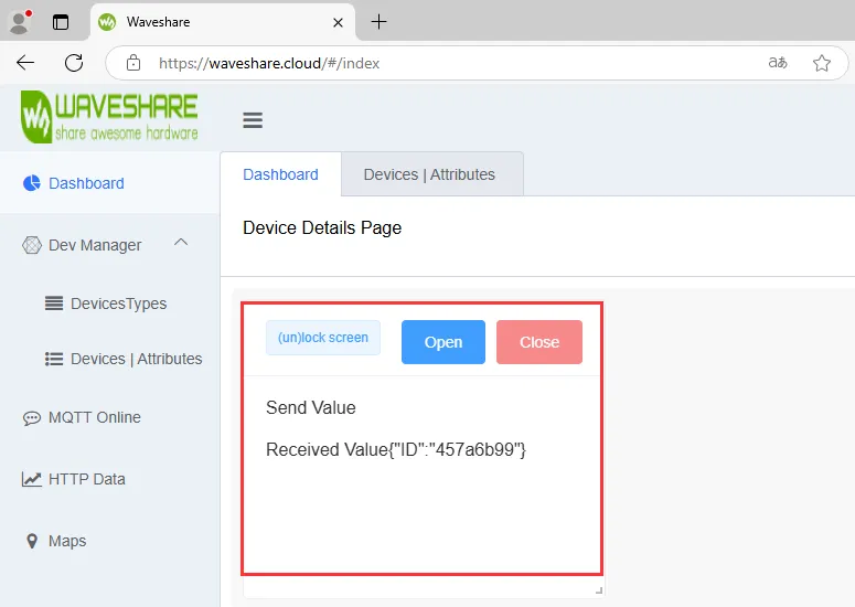
ESP32-C6-GEEK 连接微雪云成功之后即可通过 Dashboard 进行发送 MQTT 消息
-
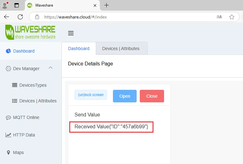
我们能在 LCD 和串口调试助手中看到我们对设备属性值(例:"key") 的变化进行了不同的反馈,并且在微雪云的设备接收值中看到 ESP32-C6-GEEK 发送至微雪云设备的数据(接受值为自己的 Client ID,后续自己可将 key 的返回值或者状态发送回微雪云),至此实现了 MQTT 的数据上行与下行、订阅主题与发布主题
17_MQTT_BLE_Keyboard
- 该例程可使用 ESP32-C6-GEEK 打开 WIFI 的 STA 模式与蓝牙,连接 WIFI 与蓝牙后,使用微雪云平台,可实现远程蓝牙锁屏与输入密码开屏,还有更多组合键等待您的开发。适用于 ESP32-C6-GEEK 集成 BLE 键盘、Wi-Fi 和 MQTT,控制 LCD 显示,测试稳定性与可靠性
代码
17_MQTT_BLE_Keyboard.ino
#include <BleKeyboard.h>
#include <WiFi.h>
#include <PubSubClient.h>
#include <SPI.h>
#include "LCD_Driver.h"
#include "GUI_Paint.h"
#include "image.h"
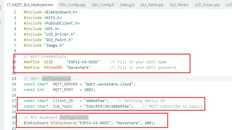
// WiFi credentials
#define SSID "ESP32-C6-GEEK" // Fill in your WIFI name
#define PASSWORD "Waveshare0755" // Fill in your WIFI password
// MQTT configuration
const char* MQTT_SERVER = "mqtt.waveshare.cloud";
const int MQTT_PORT = 1883;
const char* Client_ID = "a88e9fae"; // Defining device ID
const char* Sub_Topic = "Sub/459/54/a88e9fae"; // MQTT subscribe to topics
// BLE keyboard configuration
BleKeyboard bleKeyboard("ESP32-C6-GEEK", "Waveshare", 100);
// WiFi and MQTT clients
WiFiClient espClient;
PubSubClient client(espClient);
// Function prototypes
void setupWiFi();
void setupMQTT();
void setupBLE();
void reconnect();
void Screen_ON();
void Screen_OFF();
void callback(char* topic, byte* payload, unsigned int length);
void setup() {
// Initialize Serial communication
Serial.begin(115200);
//Initialize the LCD screen
Config_Init();
LCD_Init();
LCD_SetBacklight(100);
Paint_NewImage(LCD_WIDTH, LCD_HEIGHT, 90, WHITE);
Paint_SetRotate(90);
LCD_Clear(BLACK);
// Setup components
setupWiFi();
setupMQTT();
setupBLE();
}
void loop() {
// Wait for BLE keyboard connection
while (!bleKeyboard.isConnected()) {
delay(500);
Serial.print(".");
}
// Reconnect to MQTT if necessary
if (!client.connected()) {
reconnect();
}
// Handle MQTT messages
client.loop();
}
// Function to initialize WiFi connection
void setupWiFi() {
Paint_DrawString_EN(20, 50, "Wifi Connecting...", &Font20, BLACK, GREEN);
Serial.print("Connecting to WiFi: ");
WiFi.setSleep(true);
WiFi.begin(SSID, PASSWORD);
while (WiFi.status() != WL_CONNECTED) {
delay(500);
Serial.print(".");
}
LCD_Clear(BLACK);
Paint_DrawString_EN(20, 50, "Wifi Connected", &Font20, BLACK, GREEN);
Serial.println("\nWiFi connected");
Serial.println("IP address: " + WiFi.localIP().toString());
}
// Function to initialize MQTT connection
void setupMQTT() {
client.setServer(MQTT_SERVER, MQTT_PORT);
client.setCallback(callback);
}
// Function to initialize BLE keyboard
void setupBLE() {
bleKeyboard.begin();
Serial.println("BLE keyboard initialized");
}
// Message callback function
void callback(char* topic, byte* payload, unsigned int length) {
Serial.print("Message arrived [");
Serial.print(topic);
Serial.println("] ");
String payloadString = "";
for (int i = 0; i < length; i++) {
Serial.print((char)payload[i]);
payloadString += (char)payload[i];
}
int keyPosition = payloadString.indexOf("\"key\""); // Locate to "key",If your identifier is not "key", change it to your own!
char keyChar1 = payloadString.charAt(keyPosition + (strlen("\"key\"")+1)); // extract the first digit of the "key" value
// char keyChar2 = payloadString.charAt(keyPosition + (strlen("\"key\"")+2)); // If the extracted value is greater than one digit, add another digit
if (keyChar1 == '1') Screen_ON();
else Screen_OFF();
}
void reconnect() {
LCD_Clear(BLACK);
Paint_DrawString_EN(20, 50, "MQTT Connecting...", &Font20, BLACK, GREEN);
while (!client.connected()) {
Serial.print("Attempting MQTT connection...");
if (client.connect(Client_ID)) {
Serial.println("Connected to MQTT");
client.subscribe(Sub_Topic);
} else {
Serial.println("Failed, rc=" + String(client.state()) + " trying again in 5 seconds");
delay(5000);
}
}
LCD_Clear(BLACK);
Paint_DrawString_EN(20, 50, "MQTT Connected", &Font20, BLACK, GREEN);
}
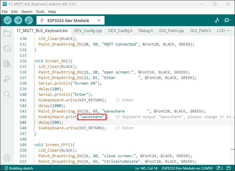
void Screen_ON(){
LCD_Clear(BLACK);
Paint_DrawString_EN(15, 20, "open screen:", &Font24, BLACK, GREEN);
Paint_DrawString_EN(15, 65, "Enter ", &Font20, BLACK, GREEN);
Serial.println("Screen ON");
delay(100);
Serial.println("Enter");
bleKeyboard.write(KEY_RETURN); // Enter
delay(1000);
Paint_DrawString_EN(15, 65, "Waveshare ", &Font20, BLACK, GREEN);
bleKeyboard.print("waveshare"); // Keyboard output "Waveshare", please change it to your open screen password!
delay(500);
bleKeyboard.write(KEY_RETURN); // Enter
}
void Screen_OFF(){
LCD_Clear(BLACK);
Paint_DrawString_EN(15, 20, "close screen:", &Font24, BLACK, GREEN);
Paint_DrawString_EN(15, 65, "Ctrl+Alt+Delete", &Font20, BLACK, GREEN);
Serial.println("Screen OFF");
bleKeyboard.press(KEY_LEFT_CTRL); // Ctrl
bleKeyboard.press(KEY_LEFT_ALT); // Alt
bleKeyboard.press(KEY_DELETE); // Delete
delay(100);
bleKeyboard.releaseAll(); // Press together
delay(500);
Paint_DrawString_EN(15, 65, "Enter ", &Font20, BLACK, GREEN);
Serial.println("Enter");
bleKeyboard.write(KEY_RETURN); // Enter
}
代码解释
-
作为 MQTT 订阅的回调函数,用于处理接收到的消息。
-
打印接收到的消息的主题,然后将接收到的字节数组转换为字符串。
-
在字符串中查找特定的 JSON 字段
“key”,如果你的标识符不是“key”,需要修改代码。 -
提取出
“key”字段的值,并根据值为 “1” 或其他情况分别调用Screen_ON或Screen_OFF函数void callback(char* topic, byte* payload, unsigned int length) {Serial.print("Message arrived [");Serial.print(topic);Serial.println("] ");String payloadString = "";for (int i = 0; i < length; i++) {Serial.print((char)payload[i]);payloadString += (char)payload[i];}int keyPosition = payloadString.indexOf("\"key\""); // Locate to "key",If your identifier is not "key", change it to your own!char keyChar1 = payloadString.charAt(keyPosition + (strlen("\"key\"")+1)); // extract the first digit of the "key" value// char keyChar2 = payloadString.charAt(keyPosition + (strlen("\"key\"")+2)); // If the extracted value is greater than one digit, add another digitif (keyChar1 == '1') Screen_ON();else Screen_OFF();} -
在串口输出正在连接的 Wi-Fi 网络名称
-
设置 Wi-Fi 模式为 STA(客户端模式),并使用指定的 SSID 和密码尝试连接。
-
在连接过程中,通过循环不断在串口输出连接状态信息,直到连接成功。
-
连接成功后,清空 LCD 屏幕并显示 “Wifi Connected”,同时在串口输出本地 IP 地址
void setupWiFi() {Paint_DrawString_EN(20, 50, "Wifi Connecting...", &Font20, BLACK, GREEN);Serial.print("Connecting to WiFi: ");WiFi.setSleep(true);WiFi.begin(SSID, PASSWORD);while (WiFi.status() != WL_CONNECTED) {delay(500);Serial.print(".");}LCD_Clear(BLACK);docsPaint_DrawString_EN(20, 50, "Wifi Connected", &Font20, BLACK, GREEN);Serial.println("\nWiFi connected");Serial.println("IP address: " + WiFi.localIP().toString());}
代码修改
-
开启的热点名称与密码要与代码中一致(2.4GHZ 或任何可用频率)
-
微雪云平台 账号注册与创建设备后,根据微雪云上新建设备的"查看地址"可以看到设备的
Client ID、Sub Topic,将它们写入例程中进行赋值,用于 ESP32-C6-GEEK 连接自己的云平台设备 -
连接的蓝牙名称与密码要与代码中一致

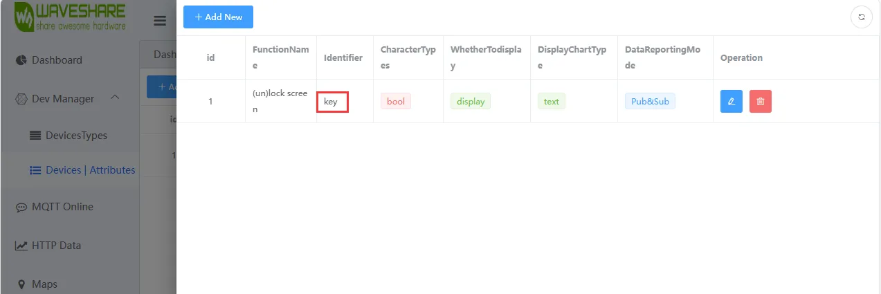
-
在 callback 函数中可以修改识别的标识符为我们自己在云平台上创建的 设备属性标识符

-
修改为自己要输入的文本或者密码
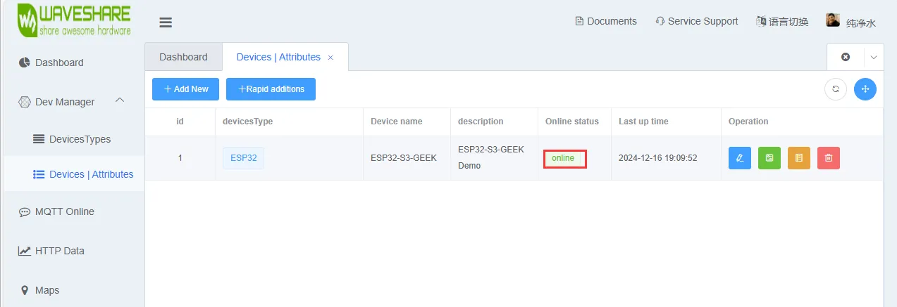
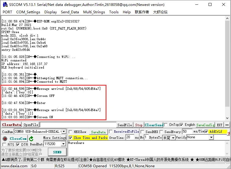
运行效果
-
烧录代码,连接上 WIFI 后,打开 PC 的蓝牙功能以配对连接设备,观察微雪云平台上设备是否进入 online 状态,若没有可以尝试刷新网页与使用 USB 转 UART 连接 PC 通过串口调试助手查看 WIFI 与 MQTT 连接情况,并且在 LCD 屏上也会显示 WIFI 与 MQTT 的连接情况

-
ESP32-C6-GEEK 连接微雪云成功之后,可通过手机端登录微雪云 Dashboard 进行远程控制

-
我们能在 LCD 和串口调试助手中看到我们对设备属性值(例:"key") 的变化进行了不同的反馈,后续还可以在 callback 函数中将按键修改成 Ctrl+C、Ctrl+V 等组合键,自己 DIY 属于你的远程控制蓝牙键盘
-
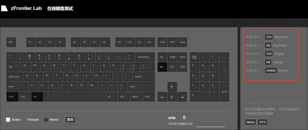
还可通过 键盘测试 的网站来测试 ESP32-C6-GEEK 蓝牙控制按下了哪些按键
-
打开键盘测试此界面,用手机端控制,键盘测试界面可显示按下了哪些按键