ESP-IDF 开发
本章节包含以下内容:
ESP-IDF 入门教程
初次接触 ESP32 ESP-IDF 开发,想要快速上手?我们为您准备了一套通用的 入门教程。
- 第0节 认识 ESP32
- 第1节 搭建环境
- 第2节 运行实例
- 第3节 创建项目
- 第4节 使用组件
- 第5节 调试程序
- 第6节 FreeRTOS
- 第7节 驱动外设
- 第8节 Wi-Fi 编程
- 第9节 BLE 编程
请注意:该教程使用 ESP32-S3-Zero 作为教学示例,所有硬件代码均基于其引脚布局。在动手实践前,建议您对照手中的开发板引脚图,确认引脚配置无误。
配置开发环境
以下说明以 Windows 10/11 为主。macOS / Linux 请参阅 Espressif 官方指南: https://docs.espressif.com/projects/esp-idf/zh_CN/latest/esp32/get-started/index.html
对于 ESP32-S3-Touch-LCD-4.3C 开发板,示例默认使用 ESP-IDF V5.5.3 如其他版本编译失败可回退至此版本测试。
-
安装 Visual Studio Code: https://code.visualstudio.com/
-
在 VS Code 中安装
ESP-IDF扩展(扩展视图 Ctrl+Shift+X,搜索 ESP-IDF 并安装)。安装完成后,侧栏会出现 Espressif 图标,打开后选择
Configure ESP-IDF Extension,进入配置向导。 -
建议使用快速(Express)配置,按需选择:
- 下载服务器:Espressif(国内镜像)或 GitHub
- ESP-IDF 版本:按项目要求选择;若无特殊需求,选用最新稳定版本。注意:部分示例在较旧/特定 IDF 版本上测试通过。
- 安装路径:尽量使用无空格且仅含 ASCII 字符的路径(例如 C:\Users<用户名>\esp),以避免路径相关问题。
-
点击
Install开始自动下载与安装 ESP-IDF、工具链和创建 Python 虚拟环境,等待安装完成提示即可。
若安装失败或需重装,可尝试删除 C:\Users\%Username%\esp 与 C:\Users\%Username%\.espressif 后重试。
示例程序
ESP-IDF 示例程序包 位于 examples/esp-idf 中
下面给出每个示例的目的、要点说明与运行效果(以便快速上手)。
| 示例程序 | 基础例程说明 | 依赖库 |
|---|---|---|
| 01_i2c | 使用 I2C 控制 IO 扩展芯片,从而周期性控制 LCD 背光的开关,形成闪烁效果。 | - |
| 02_rtc | 使用板载 RTC 芯片,实现实时时钟显示与闹钟提醒功能。 | - |
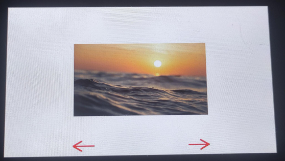
| 03_lcd | 初始化 LCD 并显示各种图形、文本和图片。 | - |
| 04_isolation_io | 通过显示器验证隔离 IO 功能是否正常。 | - |
| 05_sd | 通过显示器输出 SD 卡的挂载情况。 | - |
| 06_touch | 演示了如何使用 5 点触摸。 | - |
| 07_display_bmp | 展示了如何从 SD 卡读取并显示 BMP 图片。 | - |
| 08_wifi_scan | 扫描附近 Wi-Fi 并在屏幕显示 SSID 列表。 | - |
| 09_wifi_sta | 以 STA 模式连接 AP 并显示 IP 信息。 | - |
| 10_wifi_ap | 使用屏幕显示热点的连接情况,显示连接设备的 MAC 地址。 | - |
| 11_speaker_microphone | 录音与播放示例(codec、I2S)。 | - |
| 12_lvgl_transplant | LVGL 移植并运行官方 demo。 | LVGL |
| 13_lvgl_codec | LVGL 与音频结合示例。 | LVGL |
| 14_tcp_udp_ntp | 展示 TCP/UDP 通信与 NTP 时间同步示例。 | LVGL |
01_i2c
本示例演示如何通过 I2C 控制 IO 扩展芯片,从而周期性控制 LCD 背光的开关,形成闪烁效果。
硬件连接
- 使用 USB 线把板子接入电脑
代码
Details
/*
 * 完整代码请参考示例包中的 source code
 * The full code can be found in the example package
 */

#include "driver/i2c.h"
// ... other includes

void app_main()
{
    // Initialize the I2C interface and configure it for IO EXTENSION communication
    DEV_I2C_Init();

    /*
     * After initializing I2C, a device name and slave address need to be created.
     * This step corresponds to the specific slave device you want to communicate with.
     * Note: The function `DEV_I2C_Set_Slave_Addr` is not explicitly called here,
     * because `IO_EXTENSION_Init` already sets the slave address internally.
     * Example:
     * DEV_I2C_Set_Slave_Addr(i2c_master_dev_handle_t *dev_handle, uint8_t Addr)
     */
    IO_EXTENSION_Init();
    vTaskDelay(10 / portTICK_PERIOD_MS);
    // Enter an infinite loop to control the backlight
    while (1)
    {
        // Set the IO_EXTENSION_IO_2 pin to high (turn on the backlight)
        IO_EXTENSION_Output(IO_EXTENSION_IO_2, 1);  // Turn on backlight
        vTaskDelay(500 / portTICK_PERIOD_MS);  // Wait for 500 milliseconds

        // Set the IO_EXTENSION_IO_2 pin to low (turn off the backlight)
        IO_EXTENSION_Output(IO_EXTENSION_IO_2, 0);  // Turn off backlight
        vTaskDelay(500 / portTICK_PERIOD_MS);  // Wait for 500 milliseconds
    }
}
代码解释
- DEV_I2C_Init():初始化 I2C 驱动,通过
i2c_config_t结构体定义 SDA/SCL 引脚及频率,并调用i2c_driver_install注册驱动。 - IO_EXTENSION_Init():初始化 IO 扩展芯片,内部通过 I2C 接口设置芯片的默认寄存器状态与引脚模式。
- IO_EXTENSION_Output():通过
i2c_master_write_to_device向扩展芯片发送控制指令,利用位运算修改特定引脚的电平状态。
运行效果
- 背光按固定周期亮灭切换;串口可输出当前背光状态或 I2C 读写结果。
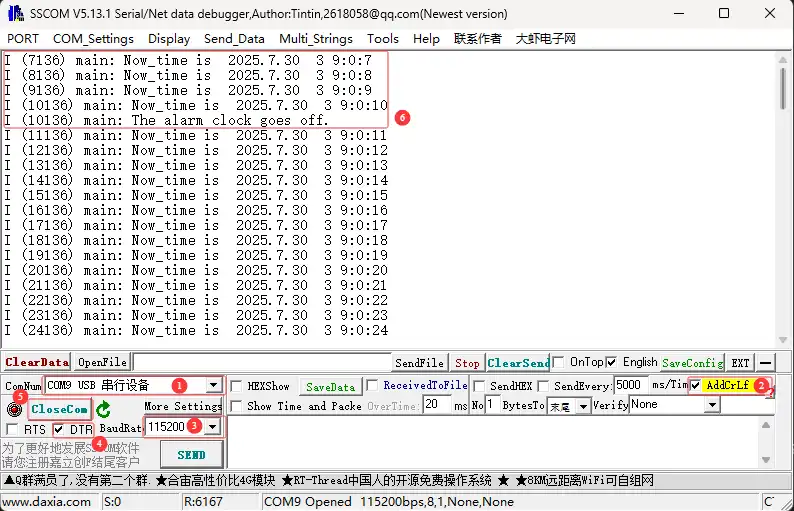
02_rtc
本示例演示板载 PCF85063 的时间读写与闹钟功能。
硬件连接
- 使用 USB 线把板子接入电脑
代码
Details
void app_main()
{
    datetime_t Now_time;

    // Initialize the I2C interface
    DEV_I2C_Init();

    // Initialize external IO extension chip
    IO_EXTENSION_Init();

    // Initialize PCF85063A RTC
    PCF85063A_Init();

    // Set current time
    PCF85063A_Set_All(Set_Time);

    // Set alarm time
    PCF85063A_Set_Alarm(Set_Alarm_Time);

    // Enable alarm interrupt
    PCF85063A_Enable_Alarm();

    while (1)
    {
        // Read current time from RTC
        PCF85063A_Read_now(&Now_time);

        // Format current time as a string
        datetime_to_str(datetime_str, Now_time);
        ESP_LOGI(TAG, "Now_time is %s", datetime_str);

        // Poll external IO pin for alarm (low level = alarm triggered)
        if (IO_EXTENSION_RTC_INT_READ() == 0)
        {
            // Re-enable alarm if repeated alarms are required
            PCF85063A_Enable_Alarm();
            ESP_LOGI(TAG, "The alarm clock goes off.");
        }

        // Wait for 1 second
        vTaskDelay(1000 / portTICK_PERIOD_MS);
    }
}
代码解释
- PCF85063A_Init():初始化 PCF85063A 实时时钟,配置 I2C 地址、使能 oscillator 并设置为 24-hour 模式。
- PCF85063A_Set_All():设置 PCF85063A 所有寄存器值,包括时间、闹钟时间、控制寄存器等。
- PCF85063A_Read_now():从 PCF85063A 读取当前时间,将 BCD 编码转换为十进制格式。
运行效果
-
串口或屏幕显示当前时间;闹钟触发时输出提示信息。
03_lcd
本示例演示 LCD 初始化与基础绘制流程,验证 RGB LCD 显示链路与帧缓冲刷新。
硬件连接
- 使用 USB 线把板子接入电脑
代码
Details
void app_main()
{
    // Initialize I2C communication and CH422G hardware interface
    DEV_I2C_Init();
    IO_EXTENSION_Init();

    // Initialize the Waveshare ESP32-S3 RGB LCD
    waveshare_esp32_s3_rgb_lcd_init();

    // Turn on the LCD backlight
    wavesahre_rgb_lcd_bl_on();
    // Uncomment the following line to turn off the backlight if needed
    // wavesahre_rgb_lcd_bl_off();

    // Allocate memory for the screen's frame buffer
    UDOUBLE Imagesize = EXAMPLE_LCD_H_RES * EXAMPLE_LCD_V_RES * 2; // Each pixel takes 2 bytes in RGB565
    UBYTE *BlackImage;
    if ((BlackImage = (UBYTE *)malloc(Imagesize)) == NULL) // Allocate memory
    {
        printf("Failed to apply for black memory...\r\n");
        exit(0); // Exit the program if memory allocation fails
    }

    // Create a new image canvas and set its background color to white
    Paint_NewImage(BlackImage, EXAMPLE_LCD_H_RES, EXAMPLE_LCD_V_RES, 0, WHITE);

    // Set the canvas scale
    Paint_SetScale(65);
    Paint_SetRotate(ROTATE);
    // Clear the canvas and fill it with a white background
    Paint_Clear(WHITE);
}
代码解释
- waveshare_esp32_s3_rgb_lcd_init():调用
esp_lcd_new_rgb_panel创建面板句柄,配置 RGB 接口时序参数以适配 4.3 寸屏幕的分辨率。 - malloc():使用
MALLOC_CAP_SPIRAM标志在外部 PSRAM 中分配 Framebuffer,解决高分辨率显示对 SRAM 占用过大的问题。 - Paint_NewImage():将分配的显示坐标与绘图上下文绑定。
运行效果
- 屏幕依次显示颜色渐变、基础图形与文字内容。
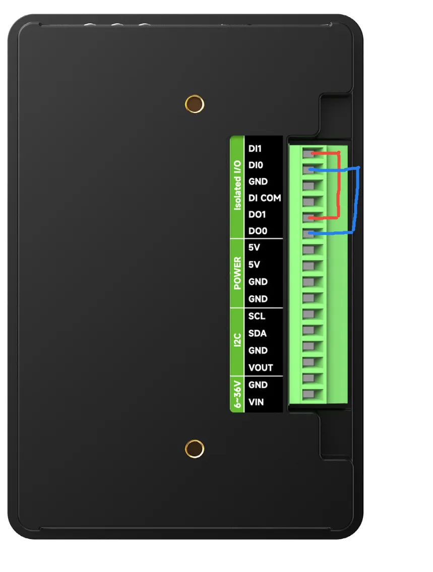
04_isolation_io
本示例验证隔离 IO 功能。
硬件连接
- 使用 USB 线把板子接入电脑;
- 根据示例连接 DO/DI 引脚测试隔离功能。
代码
Details
void app_main()
{
    // Initialize I2C communication and CH422G hardware interface
    DEV_I2C_Init();
    IO_EXTENSION_Init();

    IO_EXTENSION_IO_Mode(DI0 | DI5); // Set EXIO0 and EXIO5 to input mode

    // Initialize the Waveshare ESP32-S3 RGB LCD
    waveshare_esp32_s3_rgb_lcd_init();

    // Turn on the LCD backlight
    wavesahre_rgb_lcd_bl_on();
    // Uncomment the following line to turn off the backlight if needed
    // wavesahre_rgb_lcd_bl_off();

    // Allocate memory for the screen's frame buffer
    UDOUBLE Imagesize = EXAMPLE_LCD_H_RES * EXAMPLE_LCD_V_RES * 2; // Each pixel takes 2 bytes in RGB565
    UBYTE *BlackImage;
    if ((BlackImage = (UBYTE *)malloc(Imagesize)) == NULL) // Allocate memory
    {
        printf("Failed to apply for black memory...\r\n");
        exit(0); // Exit the program if memory allocation fails
    }

    // Create a new image canvas and set its background color to white
    Paint_NewImage(BlackImage, EXAMPLE_LCD_H_RES, EXAMPLE_LCD_V_RES, 0, WHITE);

    // Set the canvas scale
    Paint_SetScale(65);
    Paint_SetRotate(ROTATE);
    // Clear the canvas and fill it with a white background
    Paint_Clear(WHITE);
}
代码解释
- IO_EXTENSION_IO_Mode():配置扩展芯片的引脚工作模式,如将特定引脚设置为输入模式以读取隔离 DI 信号。
- IO_EXTENSION_Output():控制扩展芯片的输出引脚电平,例如驱动隔离 DO 端口输出高/低电平以控制外部继电器或负载。
- IO_EXTENSION_Read():实时读取扩展芯片输入引脚的状态,用于获取隔离 DI 端口的外部传感器或开关量反馈。
运行效果
- 烧录成功后,屏幕会根据背部接线情况显示红色还是绿色。
- 当正确接线,屏幕显示绿色。
- 当错误接线,屏幕显示红色。
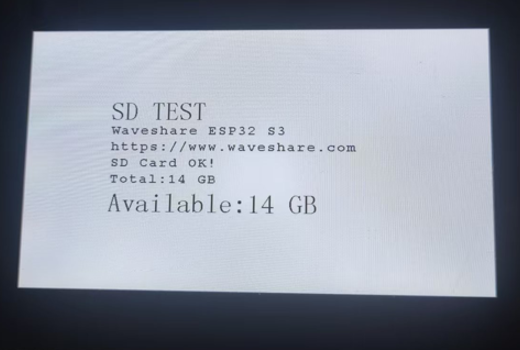
05_sd
本示例演示 SD 卡 挂载与文件系统访问,并在屏幕上显示挂载状态与基础信息。
硬件连接
- 使用 USB 线把板子接入电脑;
- 插入 TF/SD 卡.
代码
Details
void app_main()
{
    // Initialize I2C communication and configure the IO EXTENSION GPIO expander
    DEV_I2C_Init();                // Initialize the I2C bus
    IO_EXTENSION_Init();                     // Initialize IO EXTENSION chip

    IO_EXTENSION_Output(IO_EXTENSION_IO_4, 1);  // Set CS (chip select) pin high

    // Initialize the Waveshare ESP32-S3 RGB LCD
    waveshare_esp32_s3_rgb_lcd_init();
    wavesahre_rgb_lcd_bl_on();         // Turn on the LCD backlight
    // wavesahre_rgb_lcd_bl_off();     // Uncomment to turn off the backlight if needed

    // Allocate memory for the LCD's frame buffer
    UDOUBLE Imagesize = EXAMPLE_LCD_H_RES * EXAMPLE_LCD_V_RES * 2; // Each pixel uses 2 bytes in RGB565 format
    UBYTE *BlackImage;
    if ((BlackImage = (UBYTE *)malloc(Imagesize)) == NULL) // Allocate memory for the image
    {
        printf("Failed to allocate memory for frame buffer...\r\n");
        exit(0); // Exit if memory allocation fails
    }

    // Create a new image canvas and set its background color to white
    Paint_NewImage(BlackImage, EXAMPLE_LCD_H_RES, EXAMPLE_LCD_V_RES, 0, WHITE);
    Paint_SetScale(65);                // Set the canvas scale
    Paint_Clear(WHITE);                // Clear the canvas with a black background

    // Draw static text on the canvas
    Paint_DrawString_EN(150, 130, "SD TEST", &Font48, BLACK, WHITE);
    Paint_DrawString_EN(150, 180, "Waveshare ESP32 S3", &Font24, BLACK, WHITE);
    Paint_DrawString_EN(150, 210, "https://www.waveshare.com", &Font24, BLACK, WHITE);

    char Total[100], Available[100]; // Buffers for formatted text
}
代码解释
- esp_vfs_fat_sdmmc_mount():将 SD 卡挂载到虚拟文件系统(VFS),允许使用标准 POSIX 接口(如
fopen)访问 FATFS 分区。 - sd_mmc_init():初始化 SDMMC 主机控制器,配置 1-bit 或 4-bit 总线模式,并根据硬件设计设置工作频率。
- esp_vfs_fat_sdcard_unmount():将 SD 卡从虚拟文件系统中卸载,释放资源并允许重新挂载。
运行效果
-
屏幕提示挂载成功/失败,并显示卡容量、文件列表或测试文件读写结果。
06_touch
本示例演示触摸控制器驱动与 5 点触摸 读取,验证触摸坐标与屏幕坐标映射。
硬件连接
- 使用 USB 线把板子接入电脑;
- 手指在屏幕上触摸。
代码
Details
int app_main()
{
    touch_gt911_point_t point_data;  // Structure to store touch point data

    // Initialize the GT911 touch screen controller
    touch_gt911_init();

    // Initialize the Waveshare ESP32-S3 RGB LCD hardware
    waveshare_esp32_s3_rgb_lcd_init();

    // Turn on the LCD backlight
    wavesahre_rgb_lcd_bl_on();

    // Frame buffer pointers for double buffering
    void *buf1 = NULL;
    void *buf2 = NULL;

    // Retrieve pointers to the frame buffers
    waveshare_get_frame_buffer(&buf1, &buf2);
    if (buf1 == NULL || buf2 == NULL) {
        printf("Error: buf1 and buf2 are NULL!\n");
        return;
    }

    // Initialize the graphics canvas with buf2
    Paint_NewImage(buf2, EXAMPLE_LCD_H_RES, EXAMPLE_LCD_V_RES, 0, WHITE);

    // Set the scale for the graphical canvas
    Paint_SetScale(65);

    // Clear the canvas and fill it with a white background
    Paint_Clear(WHITE);

    // Copy buf2 content to buf1 to sync buffers
    memcpy(buf1, buf2, EXAMPLE_LCD_H_RES * EXAMPLE_LCD_V_RES * 2);

    // Display the initial blank screen on the LCD
    wavesahre_rgb_lcd_display(buf1);

    // Arrays to store previous touch point positions and their active states
    static uint16_t prev_x[ESP_LCD_TOUCH_MAX_POINTS];
    static uint16_t prev_y[ESP_LCD_TOUCH_MAX_POINTS];
    static bool active[ESP_LCD_TOUCH_MAX_POINTS];  // Track if a touch point is active
    static uint16_t color[ESP_LCD_TOUCH_MAX_POINTS] = {
        0x7DDF, 0xFBE4, 0x7FE0, 0xEC1D, 0xFEE0
    }; // Predefined colors for touch points
}
代码解释
- touch_gt911_init():初始化触摸控制器,配置 I2C 从机地址,并通过复位引脚触发芯片自检。
- touch_gt911_read_point():读取状态寄存器获取当前触点数量,并依次提取 5 组触点的 X/Y 坐标数据。
- Paint_DrawCircle():在指定坐标绘制一个指定半径和颜色的圆。
运行效果
烧录成功后,显示 5 点触摸读取,并根据触点坐标实时绘制圆形。
07_display_bmp
本示例从 SD 卡读取 BMP 文件并显示到屏幕,验证文件读取、解码与显示刷新链路。
硬件连接
- 使用 USB 线把板子接入电脑;
- 插入含 BMP 文件的 TF/SD 卡。
代码
Details
void app_main()
{
    touch_gt911_point_t point_data;  // Structure to store touch point data

    // Initialize the GT911 touch screen controller
    touch_gt911_init();

    // Initialize the Waveshare ESP32-S3 RGB LCD hardware
    waveshare_esp32_s3_rgb_lcd_init();

    // Turn on the LCD backlight
    wavesahre_rgb_lcd_bl_on();

    // EXAMPLE_PIN_NUM_TOUCH_INT
    // Allocate memory for the LCD's frame buffer
    UDOUBLE Imagesize = EXAMPLE_LCD_H_RES * EXAMPLE_LCD_V_RES * 2; // Each pixel uses 2 bytes in RGB565 format
    UBYTE *BlackImage;
    if ((BlackImage = (UBYTE *)malloc(Imagesize)) == NULL) // Check if memory allocation is successful
    {
        printf("Failed to allocate memory for frame buffer...\r\n");
        exit(0); // Exit if memory allocation fails
    }

    // Initialize the graphics canvas with the allocated buffer
    Paint_NewImage(BlackImage, EXAMPLE_LCD_H_RES, EXAMPLE_LCD_V_RES, 0, WHITE);

    // Set the scale for the graphical canvas
    Paint_SetScale(65);

    // Clear the canvas and fill it with a white background
    Paint_Clear(WHITE);
}
代码解释
- GUI_ReadBmp():从 SD 卡读取 BMP 文件,解析文件头获取图像尺寸与像素数据偏移。
- Paint_Clear():清除画布,填充为指定颜色。
- Paint_DrawLine():在指定坐标绘制一条线,可设置颜色、线宽、样式。
运行效果
-
屏幕显示 SD 卡中的 BMP 图片;串口输出图片信息与加载耗时。
08_wifi_scan
本示例扫描周围 Wi‑Fi 热点并在屏幕上展示 SSID/RSSI/加密方式 等信息。
硬件连接
- 使用 USB 线把板子接入电脑;
- 确保周围存在可扫描到的 Wi‑Fi。
代码
Details
int app_main()
{
    // Initialize Wi-Fi settings
    wifi_init();
    uint8_t chinese_num = 0; // Counter for Wi-Fi networks with Chinese SSIDs

    // Display static information on the LCD screen
    Paint_DrawString_EN(10, 160, "ESP32-S3-Touch-LCD-4.3C", &Font24, RED, WHITE);  // Display title
    Paint_DrawString_EN(10, 200, "WiFi SCAN Test", &Font24, RED, WHITE);          // Display Wi-Fi scan message
    Paint_DrawString_EN(10, 240, "800x480", &Font24, RED, WHITE);                // Display screen resolution
    Paint_DrawLine(400, 0, 400, 480, BLUE, DOT_PIXEL_2X2, LINE_STYLE_SOLID);  // Draw a vertical line to separate sections
    Paint_DrawString_EN(440, 0, "Scanning now...", &Font24, BLACK, WHITE); // Show scanning status message
    wavesahre_rgb_lcd_display(BlackImage);  // Refresh the display with the updated image

    // Clear the top section of the screen to display scanning results
    Paint_ClearWindows(440, 0, 800, 25, WHITE);

    // Start Wi-Fi scanning to find available networks
    wifi_scan();

    // Loop through the Wi-Fi APs found and display them on the screen
    for (int i = 0; i < DEFAULT_SCAN_LIST_SIZE; i++) {
        // Skip SSID with Chinese characters
        if (contains_chinese((const char *)ap_info[i].ssid)){
            chinese_num++;  // Increment the count for networks with Chinese SSIDs
            printf("Skipping SSID with Chinese characters: %s \r\n", ap_info[i].ssid);
        }
        else {
            // Display the SSID (Wi-Fi network name) on the screen
            Paint_DrawString_EN(440, (i - chinese_num) * 24, (const char *)ap_info[i].ssid, &Font24, BLACK, WHITE);
        }
    }

    // Update the screen with the new image (BlackImage is the framebuffer being drawn to)
    wavesahre_rgb_lcd_display(BlackImage);  // Refresh the display to show the updated list of networks
}
代码解释
- wifi_init(): 初始化 Wi-Fi 驱动程序,分配资源并启动低功耗无线射频管理任务。
- wifi_scan():启动周围接入点的扫描流程,支持全频道轮询或特定频道扫描,并配置最大返回结果数量。
- contains_chinese():检查字符串是否包含中文字符,返回
true或false。
运行效果
- 屏幕列出周围热点信息;串口输出扫描数量与每个 AP 的简要数据。
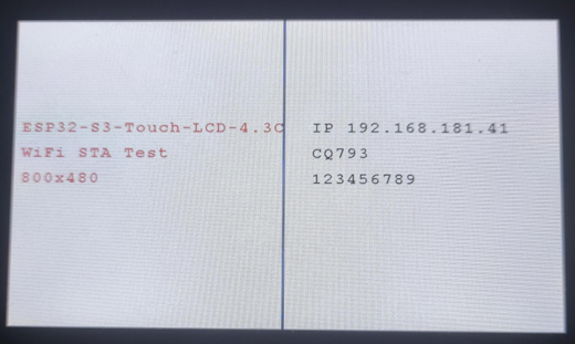
09_wifi_sta
本示例以 STA 模式连接指定 AP,并在屏幕上显示连接状态与 IP 信息。
硬件连接
- 使用 USB 线把板子接入电脑;
- 准备可连接的 Wi‑Fi(SSID/密码)。
代码
Details
#define USER_SSID "SSID"  // Wi-Fi SSID (network name)
#define USER_PASS "PASSWORD"  // Wi-Fi password

void app_main()
{
    // Initialize the Non-Volatile Storage (NVS) for Wi-Fi settings
    esp_err_t err = nvs_flash_init();
    if (err == ESP_ERR_NVS_NO_FREE_PAGES || err == ESP_ERR_NVS_NEW_VERSION_FOUND) {
        // If NVS has no free pages or a new version is found, erase and reinitialize NVS
        ESP_ERROR_CHECK(nvs_flash_erase());
        err = nvs_flash_init();
    }

    // Initialize I2C communication and IO EXTENSION hardware interface for GPIO control
    DEV_I2C_Init();  // Initialize I2C
    IO_EXTENSION_Init();   // Initialize GPIO control using the IO EXTENSION chip

    // Initialize the Waveshare ESP32-S3 RGB LCD display
    waveshare_esp32_s3_rgb_lcd_init();

    // Turn on the LCD backlight
    wavesahre_rgb_lcd_bl_on();
    // Uncomment the next line to turn off the backlight if needed
    // wavesahre_rgb_lcd_bl_off();

    // Allocate memory for the screen's framebuffer (image buffer)
    UDOUBLE Imagesize = EXAMPLE_LCD_H_RES * EXAMPLE_LCD_V_RES * 2;  // Each pixel takes 2 bytes in RGB565 format
    UBYTE *BlackImage;
    if ((BlackImage = (UBYTE *)malloc(Imagesize)) == NULL) {  // Allocate memory for the framebuffer
        printf("Failed to apply for black memory...\r\n");
        exit(0);  // Exit the program if memory allocation fails
    }

    // Create a new image canvas and set its background color to white
    Paint_NewImage(BlackImage, EXAMPLE_LCD_H_RES, EXAMPLE_LCD_V_RES, 0, WHITE);

    // Set the canvas scale and rotation for the display
    Paint_SetScale(65);  // Set the scale for the image
    Paint_SetRotate(ROTATE);  // Set the rotation (0 degrees)

    // Clear the canvas and fill it with a white background
    Paint_Clear(WHITE);

    // Initialize Wi-Fi settings (connect to the specified Wi-Fi network)
    wifi_init();

    // Display some information on the LCD screen
    Paint_DrawString_EN(10, 160, "ESP32-S3-Touch-LCD-4.3C", &Font24, RED, WHITE);  // Display title
    Paint_DrawString_EN(10, 200, "WiFi STA Test", &Font24, RED, WHITE);          // Display Wi-Fi test message
    Paint_DrawString_EN(10, 240, "800x480", &Font24, RED, WHITE);                // Display screen resolution
    Paint_DrawString_EN(440, 160, "wifi connecting......", &Font24, BLACK, WHITE); // Display Wi-Fi connection status
    Paint_DrawLine(400, 0, 400, 480, BLUE, DOT_PIXEL_2X2, LINE_STYLE_SOLID);  // Draw a vertical line on the display

    wavesahre_rgb_lcd_display(BlackImage);  // Refresh the display with the updated image (BlackImage is the framebuffer)

    // Initialize Wi-Fi in STA mode and attempt to connect to the specified SSID and password
    wifi_sta_init((uint8_t *)USER_SSID, (uint8_t *)USER_PASS, WIFI_AUTH_WPA2_PSK);

    // Update the screen with the new image (BlackImage is the framebuffer being drawn to)
    wavesahre_rgb_lcd_display(BlackImage);  // Refresh the display again to show the updated image
}
代码解释
- nvs_flash_init():初始化非易失性存储(NVS),用于持久化保存 Wi-Fi 连接配置(如 SSID 和密码)。
- wifi_sta_init():配置 Wi-Fi 为 Station 模式,并设置认证加密方式(如 WPA2_PSK),发起连接请求。
- wifi_init():初始化 Wi-Fi 驱动程序,分配资源并启动低功耗无线射频管理任务。
运行效果
-
屏幕显示连接成功与分配到的 IP;断开时提示重连状态。
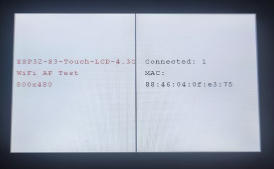
10_wifi_ap
本示例启用 SoftAP 热点,并在屏幕上显示连接设备信息(如 MAC、连接数量)。
硬件连接
- 使用 USB 线把板子接入电脑;
- 手机/电脑连接到开发板热点。
代码
Details
// Initialize SoftAP (Wi-Fi Access Point) with SSID, password, and channel
int app_main(void)
{
    wifi_ap_init((uint8_t *)USER_SSID, (uint8_t *)USER_PASS, 1);

    static uint8_t connection_num = 0;  // Variable to track the number of connected stations
    while (1)
    {
        esp_err_t ret = esp_wifi_ap_get_sta_list(&sta_list);  // Get the list of connected stations (devices)
        if (ret == ESP_OK)
        {
            // If the number of connected stations has changed, update the UI
            if (connection_num != sta_list.num)
            {
                char station_num[32];
                char station_mac[32];  // Buffer to hold formatted MAC address string


                Paint_ClearWindows(430, 160, 800, 480, WHITE);  // Clear the section of the screen displaying the connection info

                snprintf(station_num, sizeof(station_num), "Connected: %d", sta_list.num); // Format the number of connected stations
                Paint_DrawString_EN(430, 160, station_num, &Font24, BLACK, WHITE);  // Display the number of connected devices
                if (sta_list.num == 0)
                {
                    ESP_LOGE(TAG_AP, "No device connected.");  // Log error if no devices are connected
                }
                else
                {
                    for (int i = 0; i < sta_list.num; i++)
                    {
                        wifi_sta_info_t sta_info = sta_list.sta[i];  // Get station info (MAC address, RSSI, etc.)

                        // Format the MAC address and display it in the list
                        snprintf(station_mac, sizeof(station_mac), MACSTR, MAC2STR(sta_info.mac));
                        Paint_DrawString_EN(430, 200 , "MAC:", &Font24, BLACK, WHITE);  // Label for MAC address
                        Paint_DrawString_EN(430, 240 + (i * 40), station_mac, &Font24, BLACK, WHITE);  // Display MAC address

                        // Log information about the connected stations
                        ESP_LOGI(TAG_AP, "STA %d: MAC Address: " MACSTR, i, MAC2STR(sta_info.mac));  // Log MAC address
                        ESP_LOGI(TAG_AP, "STA %d: RSSI: %d", i, sta_info.rssi);  // Log signal strength (RSSI)
                    }
                }
                // Update the screen with the new image (BlackImage is the framebuffer being drawn to)
                wavesahre_rgb_lcd_display(BlackImage);  // Refresh the display again to show the updated image
                connection_num = sta_list.num;  // Update the connection number variable
            }
        }
        else
        {
            ESP_LOGE(TAG_AP, "Failed to get STA list");  // Log error if failed to get list of connected stations
        }
        // Delay for 10ms before the next loop iteration
        vTaskDelay(100);  // Short delay to avoid overloading the CPU
    }
}
代码解释
- wifi_ap_init():初始化软热点(SoftAP)模式,设置 SSID、密码及工作信道,并配置最大接入客户端数量。
- esp_wifi_ap_get_sta_list():定期查询已连接的站点列表,获取当前连接设备的数量及其硬件 MAC 地址。
- MACSTR/MAC2STR():使用格式化宏将 6 字节的原始 MAC 地址转换为易读的字符串格式,以便在 UI 上展示。
运行效果
- 屏幕显示热点状态与已连接设备信息;串口同步输出连接/断开日志。
11_speaker_microphone
本示例演示音频采集与播放链路,包含 麦克风录音 与 扬声器播放(Codec + I2S)。
硬件连接
- 使用 USB 线把板子接入电脑;
- 通过板载麦克风录音并从扬声器回放。
代码
Details
void app_main()
{
    touch_gt911_point_t point_data;
    DEV_I2C_Init();
    IO_EXTENSION_Init();
    touch_gt911_init(DEV_I2C_Get_Bus_Device());
    waveshare_esp32_s3_rgb_lcd_init();
    wavesahre_rgb_lcd_bl_on();

    // Allocate LCD frame buffer
    UDOUBLE Imagesize = EXAMPLE_LCD_H_RES * EXAMPLE_LCD_V_RES * 2;
    BlackImage = (UBYTE *)malloc(Imagesize);
    if (!BlackImage)
    {
        printf("Failed to allocate memory for frame buffer...\r\n");
        exit(0);
    }

    Paint_NewImage(BlackImage, EXAMPLE_LCD_H_RES, EXAMPLE_LCD_V_RES, 0, WHITE);
    Paint_SetScale(65);
    Paint_Clear(WHITE);

    // Draw initial red record button
    Paint_DrawCircle(405, 450, 15, RED, DOT_PIXEL_2X2, DRAW_FILL_FULL);
    Paint_DrawString_EN(100, 150, "Click to start recording", &Font48, BLACK, WHITE);
    wavesahre_rgb_lcd_display(BlackImage);

    // Initialize speaker codec
    codec_init();
    speaker_codec_volume_set(100, NULL);
    microphone_codec_gain_set(30, NULL);

    // Allocate memory for recording buffer
    record_buffer = heap_caps_malloc(BUFFER_SIZE * sizeof(int16_t), MALLOC_CAP_SPIRAM | MALLOC_CAP_8BIT);
    if (!record_buffer)
    {
        ESP_LOGE(TAG, "Failed to allocate buffer");
        vTaskDelete(NULL);
        return;
    }

    // Touch handling loop
    static uint16_t prev_x;
    static uint16_t prev_y;
    bool is_playing = false;

    while (1)
    {
        point_data = touch_gt911_read_point(1);
        if (point_data.cnt == 1)
        {
            if (prev_x == point_data.x[0] && prev_y == point_data.y[0])
            {
                continue;
            }
            else if (point_data.x[0] > 390 && point_data.x[0] < 420 &&
                     point_data.y[0] > 420 && point_data.y[0] < 480)
            {
                Paint_Clear(WHITE);
                is_playing = !is_playing;
                play_or_pause(is_playing);

                prev_x = point_data.x[0];
                prev_y = point_data.y[0];
            }
        }
        vTaskDelay(30 / portTICK_PERIOD_MS);
    }
}
代码解释
- codec_init():初始化音频编解码芯片,配置采样频率、位宽以及输入输出路由(如开启麦克风增益和扬声器功放)。
- heap_caps_malloc():在 PSRAM 中分配大容量录音缓冲区,支持长时间音频采集而不会耗尽内部 SRAM。
运行效果
-
可听到回放音频;串口输出录音/播放状态与音频参数。
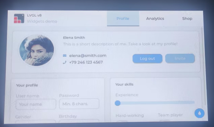
12_lvgl_transplant
本示例完成 LVGL 基础移植,验证显示驱动、触摸输入与 LVGL 刷新流程,并运行官方 demo。
硬件连接
- 使用 USB 线把板子接入电脑;
- 可触摸屏幕交互。
代码
Details
void app_main()
{
    static esp_lcd_panel_handle_t panel_handle = NULL; // Declare a handle for the LCD panel
    static esp_lcd_touch_handle_t tp_handle = NULL;

    DEV_I2C_Init(); // Initialize I2C port
    IO_EXTENSION_Init(); // Initialize the IO EXTENSION GPIO chip

    wavesahre_rgb_lcd_bl_off(); // Turn off the LCD backlight

    tp_handle = touch_gt911_init(DEV_I2C_Get_Bus_Device()); // Initialize the GT911 touch screen controller
    panel_handle = waveshare_esp32_s3_rgb_lcd_init(); // Initialize the Waveshare ESP32-S3 RGB LCD hardware
    ESP_ERROR_CHECK(lvgl_port_init(panel_handle, tp_handle)); // Initialize LVGL with the panel and touch handles

    ESP_LOGI(TAG, "Display LVGL demos");

    // Lock the mutex due to the LVGL APIs are not thread-safe
    if (lvgl_port_lock(-1)) {
        // lv_demo_stress();
        // lv_demo_benchmark();
        // lv_demo_music();
        lv_demo_widgets();
        // Release the mutex
        lvgl_port_unlock();
    }
    wavesahre_rgb_lcd_bl_on(); // Turn on the LCD backlight
}
代码解释
- lvgl_port_init():封装 LVGL 核心组件的初始化,包括内存池分配、计时器注册以及显示/输入设备的抽象绑定。
- lvgl_port_lock():由于 LVGL 核心 API 非线程安全,在跨任务调用 UI 更新时必须通过互斥锁确保原子操作。
- lv_timer_handler():UI 主循环处理函数,负责计算动画、刷新脏区域像素以及处理用户输入事件。
运行效果
- 屏幕显示 LVGL demo 界面,可触摸交互;串口输出 LVGL 初始化与刷新信息。
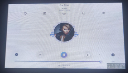
13_lvgl_codec
本示例将 LVGL UI 与音频功能结合,演示 UI 控制音量/播放状态等交互。
硬件连接
- 使用 USB 线把板子接入电脑;
- 扬声器与麦克风可用。
代码
Details
void app_main()
{
    static esp_lcd_panel_handle_t panel_handle = NULL; // Declare a handle for the LCD panel
    static esp_lcd_touch_handle_t tp_handle = NULL;

    DEV_I2C_Init(); // Initialize I2C port
    IO_EXTENSION_Init(); // Initialize the IO EXTENSION GPIO chip

    wavesahre_rgb_lcd_bl_off(); // Turn off the LCD backlight

    tp_handle = touch_gt911_init(DEV_I2C_Get_Bus_Device()); // Initialize the GT911 touch screen controller
    panel_handle = waveshare_esp32_s3_rgb_lcd_init(); // Initialize the Waveshare ESP32-S3 RGB LCD hardware
    ESP_ERROR_CHECK(lvgl_port_init(panel_handle, tp_handle)); // Initialize LVGL with the panel and touch handles

    ESP_LOGI(TAG, "Display LVGL demos");

    // Initialize SD card
    if (sd_mmc_init() == ESP_OK)
    {
        ESP_LOGI(TAG, "SD Card OK!");
        ESP_LOGI(TAG, "Click the arrow to start.");

        list_files(MOUNT_POINT"/music");
        if (mp3_num == 0)
        {
            ESP_LOGI(TAG, "No MP3 file found in SD card.");
            return;
        }
        else
        {
            ESP_LOGI(TAG, "music start");
        }
    }
    else
    {
        ESP_LOGI(TAG, "SD Card Fail!");
        return;
    }

    // Initialize speaker and audio player
    speaker_codec_init();
    speaker_codec_volume_set(50, NULL);
    speaker_player_register_callback(speaker_callback, NULL);
    speaker_player_init();

    // Lock the mutex due to the LVGL APIs are not thread-safe
    if (lvgl_port_lock(-1)) {
        user_lv_demo_music();
        // Release the mutex
        lvgl_port_unlock();
    }
    wavesahre_rgb_lcd_bl_on(); // Turn on the LCD backlight
}
代码解释
- sd_mmc_init():初始化 SDMMC 控制器并挂载 FATFS 分区,用于从 SD 卡检索和加载 MP3 音乐文件。
- speaker_player_init():创建音频播放后台任务,通过生产者-消费者模型实现音频文件的流式解码与播放。
- lv_obj_add_event_cb():为 UI 控件绑定交互回调,当用户操作滑块或按钮时,通过消息机制动态调整播放器状态。
运行效果
-
屏幕显示音频控制界面并可操作;播放状态与音量变化实时生效。
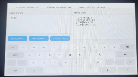
14_tcp_udp_ntp
本示例演示基础网络通信(TCP/UDP)与 NTP 对时流程,验证网络栈与时间同步功能。
硬件连接
- 使用 USB 线把板子接入电脑;
- 需先确保 Wi‑Fi 已连接。
代码
Details
/*
 * 示例代码结构参考
 * Structure reference for TCP/UDP/NTP
 */

void peripheral_init(void)
{
    // Initialize NVS
    esp_err_t ret = nvs_flash_init();
    if (ret == ESP_ERR_NVS_NO_FREE_PAGES || ret == ESP_ERR_NVS_NEW_VERSION_FOUND) {
      ESP_ERROR_CHECK(nvs_flash_erase());
      ret = nvs_flash_init();
    }
    ESP_ERROR_CHECK(ret);
    ESP_ERROR_CHECK(esp_event_loop_create_default());
    // Initialize Hardware
    DEV_I2C_Init();
    IO_EXTENSION_Init();
    // Initialize LCD and Touch
    esp_lcd_panel_handle_t panel_handle = waveshare_esp32_s3_rgb_lcd_init();
    wavesahre_rgb_lcd_bl_on();
    esp_lcd_touch_handle_t tp_handle = touch_gt911_init(DEV_I2C_Get_Bus_Device());
    // Initialize LVGL
    ESP_ERROR_CHECK(lvgl_port_init(panel_handle, tp_handle));
    // Initialize UI
    ui_init();
    ui_log("System Initialized. Waiting for WiFi...");
    // Initialize WiFi
    wifi_init_sta();
    // Wait for WiFi connection
    xEventGroupWaitBits(get_wifi_event_group(), WIFI_CONNECTED_BIT, pdFALSE, pdFALSE, portMAX_DELAY);
    // Initialize NTP
    initialize_sntp();
}
代码解释
- peripheral_init():作为系统外设初始化总入口,依次完成 NVS、事件循环、I2C 扩展、LCD/触摸、LVGL UI、Wi‑Fi 和 NTP 初始化,为后续网络通信和时间同步打好基础。
- wifi_init_sta():将 Wi‑Fi 配置为 STA 模式并发起连接,为 TCP/UDP 通信和 NTP 对时提供稳定的网络通道。
- initialize_sntp():在确认 Wi‑Fi 已联网后启动 SNTP 客户端,从上游 NTP 服务器同步系统时间,为
localtime等时间相关接口提供正确的基础时间。
运行效果
-
串口输出连接信息;使用网络调试助手设置对应 IP 地址和端口号,可以进行基本数据交互;并且屏幕显示网络状态与当前时间。