Arduino 开发
本章节包含以下部分,请按需阅读:
Arduino 入门教程
初次接触 Arduino ESP32 开发,想要快速上手?我们为您准备了一套通用的 入门教程。
- 第0节 认识 ESP32
- 第1节 安装和配置 Arduino IDE
- 第2节 Arduino 基础知识
- 第3节 数字输出/输入
- 第4节 模拟输入
- 第5节 脉冲宽度调制 (PWM)
- 第6节 串行通信 (UART)
- 第7节 I2C 通信
- 第8节 SPI 通信
- 第9节 Wi-Fi 基础用法
- 第10节 网页服务器
- 第11节 蓝牙 (Bluetooth)
- 第12节 LVGL 图形界面开发
- 第13节 综合项目
请注意:该教程使用 ESP32-S3-Zero 作为教学示例,所有硬件代码均基于其引脚布局。在动手实践前,建议您对照手中的开发板引脚图,确认引脚配置无误。
配置开发环境
1. 安装和配置 Arduino IDE
请参考 安装和配置 Arduino IDE 教程 下载安装 Arduino IDE 并添加 ESP32 支持。
2. 安装库
要运行示例,需要安装对应的库。
可从 此链接 下载 ESP32-S3-Touch-LCD-4.3C 开发板的示例程序包。包内的 arduino\libraries 目录已包含本教程所需的全部库文件。
| 库或文件名称 | 说明 | 版本 | 安装方式 |
|---|---|---|---|
| lvgl | LVGL 图形库 | v8.4.0 | 通过库管理器或手动安装 |
| lv_conf.h | LVGL 配置文件 | —— | 手动安装 |
LVGL 及其驱动库的版本之间存在较强的依赖关系。例如,为 LVGL v8 编写的驱动可能不兼容 LVGL v9。为确保示例能够稳定复现,推荐使用上表列出的特定版本。混合使用不同版本的库可能导致编译失败或运行时异常。
ESP32-S3-LCD-4.3C 所需开发板安装说明
| 板名称 | 板安装要求 | 版本号要求 |
|---|---|---|
| ESP32 by Espressif Systems | “离线”安装/“在线”安装 | 3.1.1 |
安装步骤:
-
进入已下载的 示例程序包。
-
将其
arduino\libraries目录下的所有文件夹(lvgl 和 lv_conf.h 等)复制到 Arduino 的库文件夹中。信息Arduino 库文件夹的路径通常是:
c:\Users\<用户名>\Documents\Arduino\libraries。也可以在 Arduino IDE 中通过 文件 > 首选项,查看“项目文件夹位置”来定位。库文件夹就是此路径下的
libraries文件夹。 -
其他安装方式请参考:Arduino 库管理教程。
3. Arduino 工程参数设置

示例程序
Arduino 示例程序位于 示例程序包 的 arduino/examples 目录中。
| 示例程序 | 基础例程说明 | 依赖库 |
|---|---|---|
| 01_i2c | 测试 I2C 功能 | - |
| 02_rtc | 测试 RTC 功能 | - |
| 03_lcd | 测试 LCD 功能 | - |
| 04_isolation_io | 测试 ISOLATION_IO 功能 | - |
| 05_sd | 测试 SD 卡 | - |
| 06_touch | 测试显示屏触控功能 | - |
| 07_display_bmp | 测试 SD 卡图片显示 | - |
| 08_wifi_scan | 扫描附近 WIFI,并显示 WIFI 名 | - |
| 09_wifi_sta | 测试 STA 功能 | - |
| 10_wifi_ap | 测试 AP 功能 | - |
| 11_speaker_microphone | 测试麦克风拾音功能和喇叭播放功能 | - |
| 12_lvgl_transplant | LVGL demo 测试 | LVGL |
| 13_lvgl_btn | 画一个按钮,控制 GPIO 工作 | LVGL |
| 14_lvgl_slider | 画一个滑动条,控制背光和 GPIO 输出,并显示电池电压 | LVGL |
| 15_udp_tcp_ntp | 实现 UDP/TCP 通信,并实现 NTP 时间同步 | LVGL |
01_i2c
本示例演示如何通过 I2C 控制 IO 扩展芯片,从而周期性控制 LCD 背光的开关,形成闪烁效果。
硬件连接
- 使用 USB 线把板子接入电脑
代码
01_i2c.ino
#include "src/io_extension/io_extension.h"

void setup() {
  // Initialize the IO EXTENSION device for I2C communication.
  DEV_I2C_Init();
  IO_EXTENSION_Init();
  delay(10);
}

void loop() {
  // Turn on the LCD backlight by setting IO_EXTENSION_IO_2 high.
  IO_EXTENSION_Output(IO_EXTENSION_IO_2, 1);
  delay(500);  // Wait for 500 milliseconds.

  // Turn off the LCD backlight by setting IO_EXTENSION_IO_2 low.
  IO_EXTENSION_Output(IO_EXTENSION_IO_2, 0);
  delay(500);  // Wait for 500 milliseconds.
}
代码解释
-
setup():- 该函数是初始化 I2C 通信和 IO 扩展芯片,设置 IO_EXTENSION_IO_2 引脚为输出模式。
-
loop():- 通过 IO_EXTENSION_Output 函数控制 IO_EXTENSION_IO_2 引脚的电平状态,在高电平(1)和低电平(0)之间切换,实现 LCD 背光的开启与关闭,形成每秒一次的周期性闪烁效果。
运行效果
- 屏幕无显示,连接的 LED 灯会以 1Hz 的频率亮灭
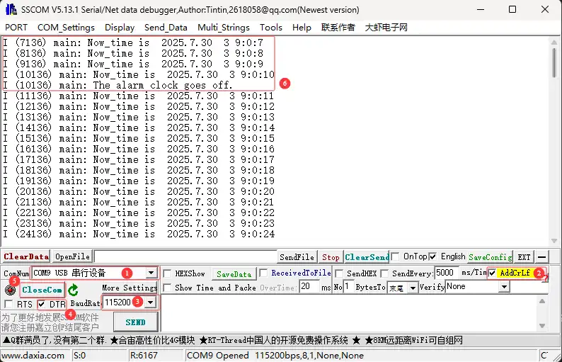
02_rtc
本示例演示如何使用板载 PCF85063 RTC 芯片,实现实时时钟显示与闹钟提醒功能。
硬件连接
- 使用 USB 线把板子接入电脑
代码
02_rtc.ino
#include "src/io_extension/io_extension.h"       // IO extension control (e.g., external interrupt input)
#include "src/rtc_pcf85063a/rtc_pcf85063a.h"     // PCF85063A RTC driver

// Initial RTC time to be set
static datetime_t Set_Time = {
    .year = 2025,
    .month = 07,
    .day = 30,
    .dotw = 3,   // Day of the week: 0 = Sunday
    .hour = 9,
    .min = 0,
    .sec = 0
};

// Alarm time to be set
static datetime_t Set_Alarm_Time = {
    .year = 2025,
    .month = 07,
    .day = 30,
    .dotw = 3,
    .hour = 9,
    .min = 0,
    .sec = 2
};

char datetime_str[256];  // Buffer to store formatted date-time string

void setup() {
  // Start Serial
  Serial.begin(115200); // Initialize serial communication at 115200 baud rate

  // Initialize the I2C interface
  DEV_I2C_Init();

  // Initialize external IO extension chip
  IO_EXTENSION_Init();

  // Initialize PCF85063A RTC
  PCF85063A_Init();

  // Set current time
  PCF85063A_Set_All(Set_Time);

  // Set alarm time
  PCF85063A_Set_Alarm(Set_Alarm_Time);

  // Enable alarm interrupt
  PCF85063A_Enable_Alarm();

}

datetime_t Now_time;
void loop() {
  // Read current time from RTC
  PCF85063A_Read_now(&Now_time);

  // Format current time as a string
  datetime_to_str(datetime_str, Now_time);
  printf("Now_time is %s\r\n", datetime_str);

  // Poll external IO pin for alarm (low level = alarm triggered)
  if (IO_EXTENSION_Rtc_Int_Read() == 0)
  {
      // Re-enable alarm if repeated alarms are required
      PCF85063A_Enable_Alarm();
      printf("The alarm clock goes off.\r\n");
  }
  delay(1000);
}
代码解释
-
setup():- 初始化串口、I2C、RTC 芯片并设置初始时间和闹钟,为程序运行做准备。
-
loop():- 不断读取当前时间并打印,同时检测闹钟是否触发,实现实时时钟与闹钟提醒功能。
运行效果
-
打开串口调试助手向 ESP32-S3-Touch-LCD-4.3C 发送消息,该设备会将收到的消息返回给串口调试助手
03_lcd
本示例演示如何初始化 LCD 并显示各种图形、文本和图片。
硬件连接
- 使用 USB 线把板子接入电脑
代码
03_lcd.ino
/*
* The LCD parameters and GPIO number used by this example can be changed in
* [rgb_lcd_port.h](components/rgb_lcd_port.h). Especially, please pay attention
* to the **vendor specific initialization**, it can be different between
* manufacturers and should consult the LCD supplier for initialization sequence
* code.
*/
#include "src/rgb_lcd_port/rgb_lcd_port.h"          // Header for Waveshare RGB LCD driver
#include "src/rgb_lcd_port/gui_paint/gui_paint.h"   // Header for graphical drawing functions
#include "src/rgb_lcd_port/image/image.h"           // Header for image resources

#define ROTATE ROTATE_0//rotate = 0, 90, 180, 270

void setup() {
  // put your setup code here, to run once:
  Serial.begin(115200);
  DEV_I2C_Init();
  IO_EXTENSION_Init();
  // Initialize the Waveshare ESP32-S3 RGB LCD
  waveshare_esp32_s3_rgb_lcd_init();
  // Turn on the LCD backlight
  wavesahre_rgb_lcd_bl_on();
  UDOUBLE Imagesize = EXAMPLE_LCD_H_RES * EXAMPLE_LCD_V_RES * 2; // Each pixel takes 2 bytes in RGB565
  UBYTE *BlackImage;
  if ((BlackImage = (UBYTE *)malloc(Imagesize)) == NULL) // Allocate memory
  {
      printf("Failed to apply for black memory...\r\n");
      exit(0); // Exit the program if memory allocation fails
  }
  // Create a new image canvas and set its background color to white
    Paint_NewImage(BlackImage, EXAMPLE_LCD_H_RES, EXAMPLE_LCD_V_RES, 0, WHITE);

    // Set the canvas scale
    Paint_SetScale(65);
    Paint_SetRotate(ROTATE);
    // Clear the canvas and fill it with a white background
    Paint_Clear(WHITE);
    if (ROTATE == ROTATE_0 || ROTATE == ROTATE_180)
    {
        // Draw gradient color stripes using RGB565 format
        // From red to blue
        Paint_DrawRectangle(1, 1, 50, 480, 0xF800, DOT_PIXEL_1X1, DRAW_FILL_FULL);
        Paint_DrawRectangle(51, 1, 100, 480, 0x7800, DOT_PIXEL_1X1, DRAW_FILL_FULL);
        Paint_DrawRectangle(101, 1, 150, 480, 0x3800, DOT_PIXEL_1X1, DRAW_FILL_FULL);
        Paint_DrawRectangle(151, 1, 200, 480, 0x1800, DOT_PIXEL_1X1, DRAW_FILL_FULL);
        Paint_DrawRectangle(201, 1, 250, 480, 0x0800, DOT_PIXEL_1X1, DRAW_FILL_FULL);


        Paint_DrawRectangle(251, 1, 300, 480, 0x07E0, DOT_PIXEL_1X1, DRAW_FILL_FULL);
        Paint_DrawRectangle(301, 1, 350, 480, 0x03E0, DOT_PIXEL_1X1, DRAW_FILL_FULL);
        Paint_DrawRectangle(351, 1, 400, 480, 0x01E0, DOT_PIXEL_1X1, DRAW_FILL_FULL);
        Paint_DrawRectangle(401, 1, 450, 480, 0x00E0, DOT_PIXEL_1X1, DRAW_FILL_FULL);
        Paint_DrawRectangle(451, 1, 500, 480, 0x0060, DOT_PIXEL_1X1, DRAW_FILL_FULL);
        Paint_DrawRectangle(501, 1, 550, 480, 0x0020, DOT_PIXEL_1X1, DRAW_FILL_FULL);

        Paint_DrawRectangle(551, 1, 600, 480, 0x001F, DOT_PIXEL_1X1, DRAW_FILL_FULL);
        Paint_DrawRectangle(601, 1, 650, 480, 0x000F, DOT_PIXEL_1X1, DRAW_FILL_FULL);
        Paint_DrawRectangle(651, 1, 700, 480, 0x0007, DOT_PIXEL_1X1, DRAW_FILL_FULL);
        Paint_DrawRectangle(701, 1, 750, 480, 0x0003, DOT_PIXEL_1X1, DRAW_FILL_FULL);
        Paint_DrawRectangle(751, 1, 800, 480, 0x0001, DOT_PIXEL_1X1, DRAW_FILL_FULL);

        // Display the gradient on the screen
        wavesahre_rgb_lcd_display(BlackImage);
        vTaskDelay(1000);

        Paint_Clear(WHITE);
        // Draw points with increasing sizes
        Paint_DrawPoint(2, 18, BLACK, DOT_PIXEL_1X1, DOT_FILL_RIGHTUP);
        Paint_DrawPoint(2, 20, BLACK, DOT_PIXEL_2X2, DOT_FILL_RIGHTUP);
        Paint_DrawPoint(2, 23, BLACK, DOT_PIXEL_3X3, DOT_FILL_RIGHTUP);
        Paint_DrawPoint(2, 28, BLACK, DOT_PIXEL_4X4, DOT_FILL_RIGHTUP);
        Paint_DrawPoint(2, 33, BLACK, DOT_PIXEL_5X5, DOT_FILL_RIGHTUP);

        // Draw solid and dotted lines
        Paint_DrawLine(20, 5, 80, 65, MAGENTA, DOT_PIXEL_2X2, LINE_STYLE_SOLID);
        Paint_DrawLine(20, 65, 80, 5, MAGENTA, DOT_PIXEL_2X2, LINE_STYLE_SOLID);
        Paint_DrawLine(148, 35, 208, 35, CYAN, DOT_PIXEL_1X1, LINE_STYLE_DOTTED);
        Paint_DrawLine(178, 5, 178, 65, CYAN, DOT_PIXEL_1X1, LINE_STYLE_DOTTED);

        // Draw rectangles (empty and filled)
        Paint_DrawRectangle(20, 5, 80, 65, RED, DOT_PIXEL_2X2, DRAW_FILL_EMPTY);
        Paint_DrawRectangle(85, 5, 145, 65, BLUE, DOT_PIXEL_2X2, DRAW_FILL_FULL);

        // Draw circles (empty and filled)
        Paint_DrawCircle(178, 35, 30, GREEN, DOT_PIXEL_1X1, DRAW_FILL_EMPTY);
        Paint_DrawCircle(240, 35, 30, GREEN, DOT_PIXEL_1X1, DRAW_FILL_FULL);

        // Draw text and numbers
        Paint_DrawString_EN(1, 70, "AaBbCc123", &Font16, RED, WHITE);
        Paint_DrawNum(1, 100, 9.87654321, &Font20, 7, WHITE, BLACK);
        Paint_DrawString_EN(1, 130, "AaBbCc123", &Font20, 0x000f, 0xfff0);
        Paint_DrawString_EN(1, 160, "AaBbCc123", &Font24, RED, WHITE);
        Paint_DrawString_CN(1, 190, "你好Abc", &Font24CN, WHITE, BLUE);

        // Update the display with the newly drawn elements (currently displaying BlackImage)
        wavesahre_rgb_lcd_display(BlackImage);
        vTaskDelay(1000); // Delay for 1000ms to allow the screen to update

        // Draw a bitmap at coordinates (0,0) with size 800x480 using the provided gImage_Bitmap
        Paint_BmpWindows(0, 0, gImage_Bitmap, 800, 480);

        // Update the screen with the updated image (BlackImage is the framebuffer being drawn to)
        wavesahre_rgb_lcd_display(BlackImage); // Refresh the display with the new content
        vTaskDelay(1000); // Delay for 1000ms to allow the screen to update

        // Draw an image resource gImage_picture at coordinates (0,0) with size 800x480
        Paint_DrawImage(gImage_picture, 0, 0, 800, 480);

        // Optionally, you can also call this to draw the bitmap, though it's commented out here:
        // Paint_DrawBitMap(gImage_picture);

        // Update the screen with the new image (BlackImage is the framebuffer being drawn to)
        wavesahre_rgb_lcd_display(BlackImage); // Refresh the display to show the updated image

    }
    else
    {
        // Draw gradient color stripes using RGB565 format
        // From red to blue
        Paint_DrawRectangle(1, 1, 480, 50, 0xF800, DOT_PIXEL_1X1, DRAW_FILL_FULL);
        Paint_DrawRectangle(1, 51,  480, 100, 0x7800, DOT_PIXEL_1X1, DRAW_FILL_FULL);
        Paint_DrawRectangle(1, 101, 480, 150, 0x3800, DOT_PIXEL_1X1, DRAW_FILL_FULL);
        Paint_DrawRectangle(1, 151, 480, 200, 0x1800, DOT_PIXEL_1X1, DRAW_FILL_FULL);
        Paint_DrawRectangle(1, 201, 480, 250, 0x0800, DOT_PIXEL_1X1, DRAW_FILL_FULL);


        Paint_DrawRectangle(1, 251, 480, 300, 0x07E0, DOT_PIXEL_1X1, DRAW_FILL_FULL);
        Paint_DrawRectangle(1, 301, 480, 350, 0x03E0, DOT_PIXEL_1X1, DRAW_FILL_FULL);
        Paint_DrawRectangle(1, 351, 480, 400, 0x01E0, DOT_PIXEL_1X1, DRAW_FILL_FULL);
        Paint_DrawRectangle(1, 401, 480, 450, 0x00E0, DOT_PIXEL_1X1, DRAW_FILL_FULL);
        Paint_DrawRectangle(1, 451, 480, 500, 0x0060, DOT_PIXEL_1X1, DRAW_FILL_FULL);
        Paint_DrawRectangle(1, 501, 480, 550, 0x0020, DOT_PIXEL_1X1, DRAW_FILL_FULL);

        Paint_DrawRectangle(1, 550, 480, 600, 0x001F, DOT_PIXEL_1X1, DRAW_FILL_FULL);
        Paint_DrawRectangle(1, 600, 480, 650, 0x000F, DOT_PIXEL_1X1, DRAW_FILL_FULL);
        Paint_DrawRectangle(1, 650, 480, 700, 0x0007, DOT_PIXEL_1X1, DRAW_FILL_FULL);
        Paint_DrawRectangle(1, 700, 480, 750, 0x0003, DOT_PIXEL_1X1, DRAW_FILL_FULL);
        Paint_DrawRectangle(1, 750, 480, 800, 0x0001, DOT_PIXEL_1X1, DRAW_FILL_FULL);

        // Display the gradient on the screen
        wavesahre_rgb_lcd_display(BlackImage);
        vTaskDelay(1000);

        Paint_Clear(WHITE);
        // Draw points with increasing sizes
        Paint_DrawPoint(2, 18, BLACK, DOT_PIXEL_1X1, DOT_FILL_RIGHTUP);
        Paint_DrawPoint(2, 20, BLACK, DOT_PIXEL_2X2, DOT_FILL_RIGHTUP);
        Paint_DrawPoint(2, 23, BLACK, DOT_PIXEL_3X3, DOT_FILL_RIGHTUP);
        Paint_DrawPoint(2, 28, BLACK, DOT_PIXEL_4X4, DOT_FILL_RIGHTUP);
        Paint_DrawPoint(2, 33, BLACK, DOT_PIXEL_5X5, DOT_FILL_RIGHTUP);

        // Draw solid and dotted lines
        Paint_DrawLine(20, 5, 80, 65, MAGENTA, DOT_PIXEL_2X2, LINE_STYLE_SOLID);
        Paint_DrawLine(20, 65, 80, 5, MAGENTA, DOT_PIXEL_2X2, LINE_STYLE_SOLID);
        Paint_DrawLine(148, 35, 208, 35, CYAN, DOT_PIXEL_1X1, LINE_STYLE_DOTTED);
        Paint_DrawLine(178, 5, 178, 65, CYAN, DOT_PIXEL_1X1, LINE_STYLE_DOTTED);

        // Draw rectangles (empty and filled)
        Paint_DrawRectangle(20, 5, 80, 65, RED, DOT_PIXEL_2X2, DRAW_FILL_EMPTY);
        Paint_DrawRectangle(85, 5, 145, 65, BLUE, DOT_PIXEL_2X2, DRAW_FILL_FULL);

        // Draw circles (empty and filled)
        Paint_DrawCircle(178, 35, 30, GREEN, DOT_PIXEL_1X1, DRAW_FILL_EMPTY);
        Paint_DrawCircle(240, 35, 30, GREEN, DOT_PIXEL_1X1, DRAW_FILL_FULL);

        // Draw text and numbers
        Paint_DrawString_EN(1, 70, "AaBbCc123", &Font16, RED, WHITE);
        Paint_DrawNum(1, 100, 9.87654321, &Font20, 7, WHITE, BLACK);
        Paint_DrawString_EN(1, 130, "AaBbCc123", &Font20, 0x000f, 0xfff0);
        Paint_DrawString_EN(1, 160, "AaBbCc123", &Font24, RED, WHITE);
        Paint_DrawString_CN(1, 190, "你好Abc", &Font24CN, WHITE, BLUE);

        // Update the display with the newly drawn elements (currently displaying BlackImage)
        wavesahre_rgb_lcd_display(BlackImage);
        vTaskDelay(1000); // Delay for 1000ms to allow the screen to update

        // Draw a bitmap at coordinates (0,0) with size 800x480 using the provided gImage_Bitmap
        Paint_BmpWindows(0, 0, gImage_Bitmap_90, 480, 800);

        // Update the screen with the updated image (BlackImage is the framebuffer being drawn to)
        wavesahre_rgb_lcd_display(BlackImage); // Refresh the display with the new content
        vTaskDelay(1000); // Delay for 1000ms to allow the screen to update

        // Draw an image resource gImage_picture at coordinates (0,0) with size 800x480
        Paint_DrawImage(gImage_picture_90, 0, 0, 480, 800);

        // Optionally, you can also call this to draw the bitmap, though it's commented out here:
        // Paint_DrawBitMap(gImage_picture);

        // Update the screen with the new image (BlackImage is the framebuffer being drawn to)
        wavesahre_rgb_lcd_display(BlackImage); // Refresh the display to show the updated image


    }
}

void loop() {
  // put your main code here, to run repeatedly:

}
代码解释
-
setup():- 完成 LCD 初始化、显存分配,并依次演示颜色渐变、点线图形、矩形圆形、文字数字及图片的显示效果。
-
Paint_NewImage():- 画布创建:设置内存作为绘图帧缓冲区。
-
Paint_DrawRectangle():- 矩形绘制:用于绘制颜色条纹等。
-
Paint_DrawString_EN():- 文本渲染:用于绘制英文字符串。都绘制不同的元素,然后调用 wavesahre_rgb_lcd_display() 刷新屏幕。
运行效果
- 屏幕先显示彩色渐变条,然后依次展示点、线、矩形、圆、文字、数字,最后全屏显示两张图片。
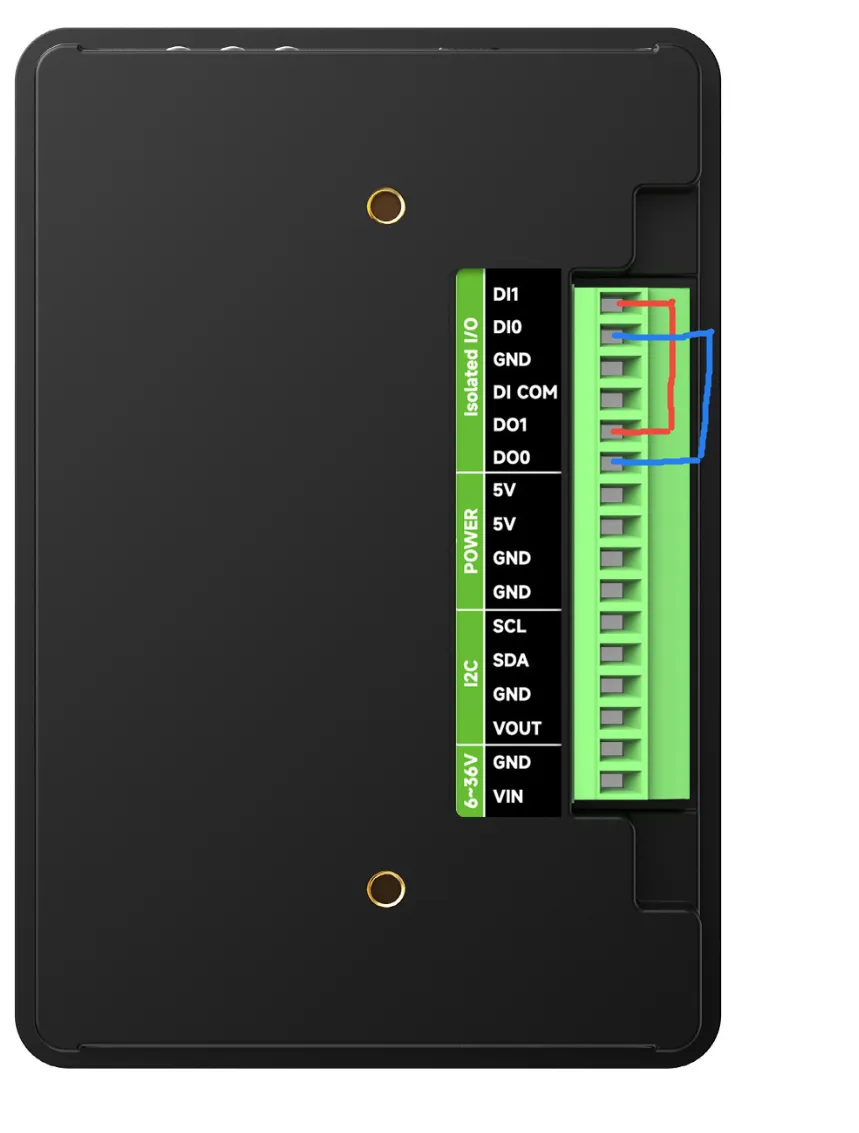
04_isolation_io
本示例通过显示器验证隔离 IO 功能是否正常。
硬件连接
- 使用 USB 线把板子接入电脑
- 在开发板背部将 DO0->DI0 DO1->DI1 连接
代码
04_isolation_io.ino
/*
* The LCD parameters and GPIO number used by this example can be changed in
* [rgb_lcd_port.h](components/rgb_lcd_port.h). Especially, please pay attention
* to the **vendor specific initialization**, it can be different between
* manufacturers and should consult the LCD supplier for initialization sequence
* code.
*/
#include "src/rgb_lcd_port/rgb_lcd_port.h"              // Header for Waveshare RGB LCD driver
#include "src/rgb_lcd_port/gui_paint/gui_paint.h"       // Header for graphical drawing functions
#include "src/rgb_lcd_port/image/image.h"               // Header for image resources

#define ROTATE ROTATE_0//rotate = 0, 90, 180, 270

void setup() {
  // put your setup code here, to run once:
  Serial.begin(115200);
  DEV_I2C_Init();
  IO_EXTENSION_Init();
  IO_EXTENSION_IO_Mode(0xDE); // Set EXIO0 and EXIO5 as input modes.

  // Initialize the Waveshare ESP32-S3 RGB LCD
  waveshare_esp32_s3_rgb_lcd_init();
  // Turn on the LCD backlight
  wavesahre_rgb_lcd_bl_on();

  UDOUBLE Imagesize = EXAMPLE_LCD_H_RES * EXAMPLE_LCD_V_RES * 2; // Each pixel takes 2 bytes in RGB565
  UBYTE *BlackImage;
  if ((BlackImage = (UBYTE *)malloc(Imagesize)) == NULL) // Allocate memory
  {
      printf("Failed to apply for black memory...\r\n");
      exit(0); // Exit the program if memory allocation fails
  }
  // Create a new image canvas and set its background color to white
    Paint_NewImage(BlackImage, EXAMPLE_LCD_H_RES, EXAMPLE_LCD_V_RES, 0, WHITE);

    // Set the canvas scale
    Paint_SetScale(65);
    Paint_SetRotate(ROTATE);
    // Clear the canvas and fill it with a white background
    Paint_Clear(WHITE);
    uint8_t io[2] = {0}, DI_flag = 0, num = 0;
    while (1)
    {
        IO_EXTENSION_Output(DO0, 1);
        IO_EXTENSION_Output(DO1, 0);
        vTaskDelay(10 / portTICK_PERIOD_MS);
        io[0] = IO_EXTENSION_Input(DI0); // Read DI0
        io[1] = IO_EXTENSION_Input(DI1); // Read DI1
        // Check if both pins match expected values
        if (io[0] == 1 && io[1] == 0)
        {
            DI_flag++; // Increment DI flag
        }

        IO_EXTENSION_Output(DO0, 0);
        IO_EXTENSION_Output(DO1, 1);
        vTaskDelay(10 / portTICK_PERIOD_MS);
        io[0] = IO_EXTENSION_Input(DI0); // Read DI0
        io[1] = IO_EXTENSION_Input(DI1); // Read DI1
        // Check again if both pins match expected values
        if (io[0] == 0 && io[1] == 1)
        {
            DI_flag++; // Increment DI flag
        }
        printf("DI_flag:%d\r\n",DI_flag);
        // If both conditions are met, DI & DO are working
        if (DI_flag >= 2)
        {
            printf("DI & DO OK!!!\r\n"); // DI and DO are functioning properly
            Paint_Clear(GREEN);
            // Display the gradient on the screen
            wavesahre_rgb_lcd_display(BlackImage);
            break;
        }
        else
        {
            num++;        // Add 1 to the count
            DI_flag=0;
            if (num == 3) // If the test fails three times, we quit
            {
                printf("DI & DO Failure!!!\r\n"); // DI and DO are not functioning
                Paint_Clear(RED);
                // Display the gradient on the screen
                wavesahre_rgb_lcd_display(BlackImage);
                break;
            }
        }
    }
}

void loop() {
  // put your main code here, to run repeatedly:

}
代码解释
-
setup():- 函数初始化串口、I2C、IO 扩展、LCD 屏幕,然后通过控制 DO 引脚并检测 DI 引脚的状态,测试 DI/DO 功能是否正常,并根据测试结果在 RGB LCD 屏幕上显示绿色(测试通过)或红色(测试失败)。
-
Serial.begin(115200):- 初始化串口通信(用于打印调试信息,波特率 115200)。
-
DEV_I2C_Init():- 初始化 I2C 总线(通常用于连接传感器、显示屏等)。
-
IO_EXTENSION_Init():- 初始化 IO 扩展芯片(扩展更多的 GPIO,比如 DI/DO)。
运行效果
- 烧录成功后,屏幕会根据背部接线情况显示红色还是绿色。
- 当正确接线,屏幕显示绿色。
- 当错误接线,屏幕显示红色。
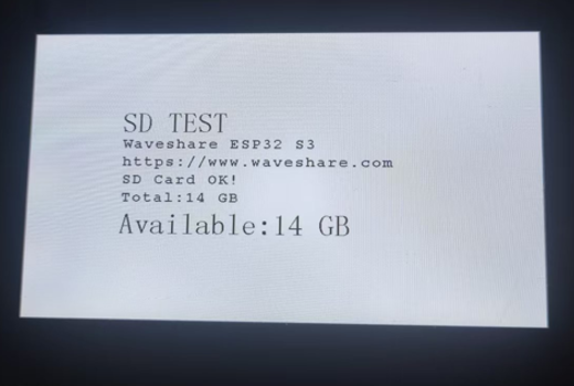
05_sd
本示例通过显示器输出 SD 卡的挂载情况
硬件连接
- 使用 USB 线把板子接入电脑
- 将 Micro SD 卡接入 ESP32-S3-Touch-LCD-4.3C 中
代码
05_sd.ino
/*
* Mount an SD card, output related parameters via serial,unmount the SD card,
* and display memory information on the screen.
*/
#include "src/rgb_lcd_port/rgb_lcd_port.h"          // Header for Waveshare RGB LCD driver
#include "src/rgb_lcd_port/gui_paint/gui_paint.h"   // Header for graphical drawing functions
#include "src/rgb_lcd_port/image/image.h"           // Header for image resources
#include "src/user_sd/user_sd.h"              // Header for SD card operations

void setup() {
  // put your setup code here, to run once:
  Serial.begin(115200);
  DEV_I2C_Init();
  IO_EXTENSION_Init();
  delay(10);
  IO_EXTENSION_Output(IO_EXTENSION_IO_4, 1);  // Set CS (chip select) pin high

  // Initialize the Waveshare ESP32-S3 RGB LCD
  waveshare_esp32_s3_rgb_lcd_init();
  // Turn on the LCD backlight
  wavesahre_rgb_lcd_bl_on();
  UDOUBLE Imagesize = EXAMPLE_LCD_H_RES * EXAMPLE_LCD_V_RES * 2; // Each pixel takes 2 bytes in RGB565
  UBYTE *BlackImage;
  if ((BlackImage = (UBYTE *)heap_caps_malloc(Imagesize, MALLOC_CAP_SPIRAM)) == NULL) // Allocate memory
  {
      printf("Failed to apply for black memory...\r\n");
      exit(0); // Exit the program if memory allocation fails
  }
  // Create a new image canvas and set its background color to white
  Paint_NewImage(BlackImage, EXAMPLE_LCD_H_RES, EXAMPLE_LCD_V_RES, 0, WHITE);

  // Set the canvas scale
  Paint_SetScale(65);
  Paint_Clear(BLACK);                // Clear the canvas with a black background

  // Draw static text on the canvas
  Paint_DrawString_EN(150, 130, "SD TEST", &Font48, CYAN, BLACK);
  Paint_DrawString_EN(150, 180, "Waveshare ESP32 S3", &Font24, CYAN, BLACK);
  Paint_DrawString_EN(150, 210, "https://www.waveshare.com", &Font24, CYAN, BLACK);
  char Total[100], Available[100]; // Buffers for formatted text
  if (sd_mmc_init() == ESP_OK) // Initialize SD card
  {
      Paint_DrawString_EN(150, 240, "SD Card OK!", &Font24, CYAN, BLACK); // Indicate SD card success

      uint64_t total, available; // Variables to store total and available space
      read_sd_capacity(&total, &available); // Read SD card capacity
      printf("Total:%d MB,Available:%d MB\r\n", (int)total / 1024, (int)available / 1024);

      // Format total space into a human-readable string
      if (((int)total / 1024) > 1024)
          sprintf(Total, "Total:%d GB", (int)total / 1024 / 1024);
      else
          sprintf(Total, "Total:%d MB", (int)total / 1024);

      // Format available space into a human-readable string
      if (((int)available / 1024) > 1024)
          sprintf(Available, "Available:%d GB", (int)available / 1024 / 1024);
      else
          sprintf(Available, "Available:%d MB", (int)available / 1024);

      // Draw the total and available space information on the canvas
      Paint_DrawString_EN(150, 270, Total, &Font24, CYAN, BLACK);
      Paint_DrawString_EN(150, 300, Available, &Font48, CYAN, BLACK);

      printf("Filesystem unmount\r\n");
      sd_mmc_unmount(); // Unmount the SD card
  }
  else
      Paint_DrawString_EN(150, 240, "SD Card Fail!", &Font24, CYAN, BLACK);

  // Display the prepared canvas on the LCD
  wavesahre_rgb_lcd_display(BlackImage);
}

void loop() {
  // put your main code here, to run repeatedly:

}
代码解释
-
setup():- 负责初始化所有必要的硬件和通信接口,包括串口、I2C、IO 扩展芯片和 LCD 屏幕。执行 SD 卡测试:尝试挂载 SD 卡,如果成功,则读取、计算并显示其总容量可用容量信息到 LCD 屏幕和串口,随后立即卸载 SD 卡。
-
sd_mmc_init():- 尝试挂载 SD 卡文件系统。
-
read_sd_capacity():- 从已挂载的 SD 卡读取总存储空间和可用存储空间。
-
sd_mmc_unmount():- 卸载 SD 卡文件系统,释放相关资源。
运行效果
-
烧录成功后,屏幕显示 SD 卡容量 ,若没插上 SD 卡则显示* SD Card Fail!
06_touch
本示例演示了如何使用 5 点触摸。
硬件连接
- 使用 USB 线把板子接入电脑
代码
06_touch.ino
/*
* Performs a five-point touch test and demonstrates basic usage of double buffering.
*/
#include "src/rgb_lcd_port/rgb_lcd_port.h"    // Header for Waveshare RGB LCD driver
#include "src/rgb_lcd_port/gui_paint/gui_paint.h"       // Header for graphical drawing functions
#include "src/gt911/gt911.h"           // Header for touch screen operations (GT911)

void setup() {
  touch_gt911_point_t point_data;  // Structure to store touch point data

  Serial.begin(115200);
  DEV_I2C_Init();
  IO_EXTENSION_Init();
  // Initialize the GT911 touch screen controller
  touch_gt911_init(DEV_I2C_Get_Bus_Device());

  // Initialize the Waveshare ESP32-S3 RGB LCD
  waveshare_esp32_s3_rgb_lcd_init();
  // Turn on the LCD backlight
  wavesahre_rgb_lcd_bl_on();
  // Frame buffer pointers for double buffering
  void *buf1 = NULL;
  void *buf2 = NULL;

  // Retrieve pointers to the frame buffers
  waveshare_get_frame_buffer(&buf1, &buf2);
  if (buf1 == NULL || buf2 == NULL) {
      printf("Error: buf1 and buf2 are NULL!\n");
      return;
  }

  // Initialize the graphics canvas with buf2
  Paint_NewImage((uint8_t *)buf2, EXAMPLE_LCD_H_RES, EXAMPLE_LCD_V_RES, 0, WHITE);

  // Set the scale for the graphical canvas
  Paint_SetScale(65);

  // Clear the canvas and fill it with a white background
  Paint_Clear(WHITE);

  // Copy buf2 content to buf1 to sync buffers
  memcpy(buf1, buf2, EXAMPLE_LCD_H_RES * EXAMPLE_LCD_V_RES * 2);

  // Display the initial blank screen on the LCD
  wavesahre_rgb_lcd_display((uint8_t *)buf1);

  // Arrays to store previous touch point positions and their active states
  static uint16_t prev_x[ESP_LCD_TOUCH_MAX_POINTS];
  static uint16_t prev_y[ESP_LCD_TOUCH_MAX_POINTS];
  static bool active[ESP_LCD_TOUCH_MAX_POINTS];  // Track if a touch point is active
  static uint16_t color[ESP_LCD_TOUCH_MAX_POINTS] = {
      0x7DDF, 0xFBE4, 0x7FE0, 0xEC1D, 0xFEE0
  }; // Predefined colors for touch points

  // Flag to toggle between the two buffers
  bool flag = true;

  // Main application loop
  while (1)
  {
      // Read the touch points from the touchscreen controller
      point_data = touch_gt911_read_point(ESP_LCD_TOUCH_MAX_POINTS);

      // Process each touch point
      for (int i = 0; i < ESP_LCD_TOUCH_MAX_POINTS; i++)
      {
          if (i < point_data.cnt) // If a valid touch point exists
          {
              if (prev_x[i] != 0 && prev_y[i] != 0)
              {
                  // Clear the previously drawn circle for this touch point
                  Paint_DrawCircle(prev_x[i], prev_y[i], 30, WHITE,
                                    DOT_PIXEL_1X1, DRAW_FILL_FULL);
              }

              // Update the previous touch point position
              prev_x[i] = point_data.x[i];
              prev_y[i] = point_data.y[i];
              active[i] = true;  // Mark the point as active

              // Log the touch point coordinates
              printf("Touch position %d: %d,%d %d", i,
                        point_data.x[i], point_data.y[i], point_data.cnt);

              // Draw a circle at the new touch point with a unique color
              Paint_DrawCircle(point_data.x[i], point_data.y[i], 30, color[i],
                                DOT_PIXEL_1X1, DRAW_FILL_FULL);
          }
          else
          {
              // If no longer active, clear the circle for this touch point
              if (active[i]) {
                  Paint_DrawCircle(prev_x[i], prev_y[i], 30, WHITE,
                                    DOT_PIXEL_1X1, DRAW_FILL_FULL);
                  active[i] = false;  // Mark the point as inactive
              }
          }
      }

      // Display the updated buffer
      if (flag)
      {
          // Small delay to reduce screen tearing
          vTaskDelay(20);

          // Display the content from buf2
          wavesahre_rgb_lcd_display((uint8_t *)buf2);

          // Sync buf2 content to buf1
          memcpy(buf1, buf2, EXAMPLE_LCD_H_RES * EXAMPLE_LCD_V_RES * 2);

          // Select buf1 as the active drawing buffer
          Paint_SelectImage((uint8_t *)buf1);
          flag = false;
      }
      else
      {
          // Small delay to reduce screen tearing
          vTaskDelay(20);

          // Display the content from buf1
          wavesahre_rgb_lcd_display((uint8_t *)buf1);

          // Sync buf1 content to buf2
          memcpy(buf2, buf1, EXAMPLE_LCD_H_RES * EXAMPLE_LCD_V_RES * 2);

          // Select buf2 as the active drawing buffer
          Paint_SelectImage((uint8_t *)buf2);
          flag = true;
      }
  }
}

void loop() {
  // put your main code here, to run repeatedly:

}
代码解释
-
setup():- 初始化串口、I2C、IO 扩展,设置触摸屏和 LCD 屏幕,配置双缓冲区。
-
touch_gt911_read_point():- 触摸读取:获取当前屏幕上所有有效的触摸点坐标和数量。
-
waveshare_rgb_lcd_display():- 将缓存区内容显示到屏幕上。
运行效果
-
烧录成功后,可以实现五点触摸功能。
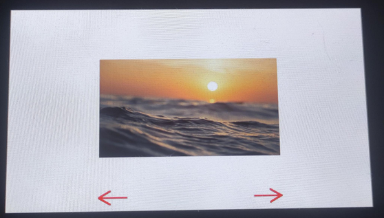
07_display_bmp
本示例展示了如何从 SD 卡读取并显示 BMP 图片。
硬件连接
- 使用 USB 线把板子接入电脑
- 将存好图片的 Micro SD 卡接入 ESP32-S3-Touch-LCD-4.3C 中
代码
07_display_bmp.ino
/*
* Read BMP files from the SD card and display on the screen.
* Use the touchscreen to switch between images.
*/
#include "src/rgb_lcd_port/rgb_lcd_port.h"              // Header for Waveshare RGB LCD driver
#include "src/rgb_lcd_port/gui_paint/gui_paint.h"       // Header for graphical drawing functions
#include "src/gt911/gt911.h"           // Header for touch screen operations (GT911)
#include "src/rgb_lcd_port/gui_paint/gui_bmp.h"         // Header for BMP image handling
#include "src/user_sd/user_sd.h"           //

#define MAX_BMP_FILES 50  // Maximum number of BMP files supported
static char *BmpPath[MAX_BMP_FILES]; // Array to store full paths of BMP files
static uint8_t bmp_num; // Counter for the number of BMP files found

/**
 * Function to list all BMP files in a given directory.
 *
 * @param base_path The base directory to search for BMP files.
 */
void list_files(const char *base_path) {
    // Open the specified directory
    File dir = SD_MMC.open(base_path);
    if (!dir) {
        Serial.println("Failed to open directory!"); // Print an error if the directory can't be opened
        return;
    }

    // Check if the provided path is a valid directory
    if (!dir.isDirectory()) {
        Serial.println("Provided path is not a directory!"); // Print an error if the path isn't a directory
        dir.close();
        return;
    }

    int i = 0; // Initialize file counter
    static char mount_point[] = MOUNT_POINT; // Mount point for the SD card
    File file = dir.openNextFile(); // Open the first file in the directory

    // Iterate through the directory and process files
    while (file && i < MAX_BMP_FILES) {
        if (!file.isDirectory()) { // Skip directories
            const char *file_name = file.name(); // Get the name of the current file
            size_t len = strlen(file_name);

            // Check if the file extension is ".bmp" (case insensitive)
            if (len > 4 && strcasecmp(&file_name[len - 4], ".bmp") == 0) {
                size_t length = strlen(mount_point) + strlen(file_name) + 2; // Calculate memory needed for full path
                BmpPath[i] = (char *)malloc(length); // Allocate memory for the full path
                if (BmpPath[i]) {
                    // Combine mount point and file name into the full path
                    snprintf(BmpPath[i], length, "%s/%s", mount_point, file_name);
                    i++; // Increment the file counter
                } else {
                    Serial.println("Memory allocation failed for BMP path!"); // Print an error if memory allocation fails
                }
            }
        }
        file.close(); // Close the current file
        file = dir.openNextFile(); // Open the next file in the directory
    }

    bmp_num = i; // Set the number of BMP files found
    Serial.print("Found BMP files: ");
    Serial.println(bmp_num); // Print the number of BMP files found

    dir.close(); // Close the directory
}


void setup() {
  touch_gt911_point_t point_data;  // Structure to store touch point data

  Serial.begin(115200);
  DEV_I2C_Init();
  IO_EXTENSION_Init();
  // Initialize the GT911 touch screen controller
  touch_gt911_init(DEV_I2C_Get_Bus_Device());

  // Initialize the Waveshare ESP32-S3 RGB LCD
  waveshare_esp32_s3_rgb_lcd_init();
  // Turn on the LCD backlight
  wavesahre_rgb_lcd_bl_on();
  // EXAMPLE_PIN_NUM_TOUCH_INT
    // Allocate memory for the LCD's frame buffer
    UDOUBLE Imagesize = EXAMPLE_LCD_H_RES * EXAMPLE_LCD_V_RES * 2; // Each pixel uses 2 bytes in RGB565 format
    UBYTE *BlackImage;
    if ((BlackImage = (UBYTE *)malloc(Imagesize)) == NULL) // Check if memory allocation is successful
    {
        printf("Failed to allocate memory for frame buffer...\r\n");
        exit(0); // Exit if memory allocation fails
    }

    // Initialize the graphics canvas with the allocated buffer
    Paint_NewImage(BlackImage, EXAMPLE_LCD_H_RES, EXAMPLE_LCD_V_RES, 0, WHITE);

    // Set the scale for the graphical canvas
    Paint_SetScale(65);

    // Clear the canvas and fill it with a white background
    Paint_Clear(WHITE);

    // Initialize SD card
    if (sd_mmc_init() == ESP_OK)
    {
        Paint_DrawString_EN(200, 200, "SD Card OK!", &Font24, BLACK, WHITE); // Display SD card success message
        Paint_DrawString_EN(200, 240, "Click the arrow to start.", &Font24, BLACK, WHITE); // Display prompt

        // Draw navigation arrows
        Paint_DrawLine(540, 450, 600, 450, RED, DOT_PIXEL_2X2, LINE_STYLE_SOLID);
        Paint_DrawLine(575, 435, 600, 450, RED, DOT_PIXEL_2X2, LINE_STYLE_SOLID); // Right arrow
        Paint_DrawLine(575, 465, 600, 450, RED, DOT_PIXEL_2X2, LINE_STYLE_SOLID);

        // List BMP files from the SD card
        list_files("/");
        if (bmp_num == 0)
        {
            Paint_DrawString_EN(200, 280, "There is no BMP file in the memory card.", &Font24, RED, WHITE); // Display prompt
            wavesahre_rgb_lcd_display(BlackImage);
            return;
        }
        else
        {
            // Draw navigation arrows
            Paint_DrawLine(540, 450, 600, 450, RED, DOT_PIXEL_2X2, LINE_STYLE_SOLID);
            Paint_DrawLine(575, 435, 600, 450, RED, DOT_PIXEL_2X2, LINE_STYLE_SOLID); // Right arrow
            Paint_DrawLine(575, 465, 600, 450, RED, DOT_PIXEL_2X2, LINE_STYLE_SOLID);

            // Display the initial image on the screen
            wavesahre_rgb_lcd_display(BlackImage);
        }
    }
    else
    {
        // If SD card initialization fails
        Paint_DrawString_EN(200, 200, "SD Card Fail!", &Font24, BLACK, WHITE);
        wavesahre_rgb_lcd_display(BlackImage);
        return;

    }

    // Initial touch point variables
    int8_t i = 0;
    static uint16_t prev_x;
    static uint16_t prev_y;

    while (1)
    {
        point_data = touch_gt911_read_point(1);  // Read touch data
        if (point_data.cnt == 1)  // Check if touch is detected
        {
            // If touch position hasn't changed, continue the loop
            if ((prev_x == point_data.x[0]) && (prev_y == point_data.y[0]))
            {
                continue;
            }

            // If touch is within the left navigation area, switch to the previous image
            if (point_data.x[0] > 200 && point_data.x[0] < 260 && point_data.y[0] > 420 && point_data.y[0] < 480)
            {
                i--;
                if (i < 0)  // If index goes below 0, wrap around to the last image
                {
                    i = bmp_num - 1;
                }
                Paint_Clear(WHITE);  // Clear the screen
                GUI_ReadBmp(200, 123, BmpPath[i]);  // Read and display the previous BMP image

                // Draw navigation arrows
                Paint_DrawLine(200, 450, 260, 450, RED, DOT_PIXEL_2X2, LINE_STYLE_SOLID); // Left arrow
                Paint_DrawLine(200, 450, 225, 435, RED, DOT_PIXEL_2X2, LINE_STYLE_SOLID);
                Paint_DrawLine(200, 450, 225, 465, RED, DOT_PIXEL_2X2, LINE_STYLE_SOLID);

                // Right arrow
                Paint_DrawLine(540, 450, 600, 450, RED, DOT_PIXEL_2X2, LINE_STYLE_SOLID);
                Paint_DrawLine(575, 435, 600, 450, RED, DOT_PIXEL_2X2, LINE_STYLE_SOLID);
                Paint_DrawLine(575, 465, 600, 450, RED, DOT_PIXEL_2X2, LINE_STYLE_SOLID);

                wavesahre_rgb_lcd_display(BlackImage);  // Update display

                prev_x = point_data.x[0];  // Update previous touch position
                prev_y = point_data.y[0];
            }
            // If touch is within the right navigation area, switch to the next image
            else if (point_data.x[0] > 540 && point_data.x[0] < 600 && point_data.y[0] > 420 && point_data.y[0] < 480)
            {
                i++;
                if (i > bmp_num - 1)  // If index exceeds the number of images, wrap around to the first image
                {
                    i = 0;
                }
                Paint_Clear(WHITE);  // Clear the screen
                GUI_ReadBmp(200, 123, BmpPath[i]);  // Read and display the next BMP image

                // Draw navigation arrows
                Paint_DrawLine(200, 450, 260, 450, RED, DOT_PIXEL_2X2, LINE_STYLE_SOLID); // Left arrow
                Paint_DrawLine(200, 450, 225, 435, RED, DOT_PIXEL_2X2, LINE_STYLE_SOLID);
                Paint_DrawLine(200, 450, 225, 465, RED, DOT_PIXEL_2X2, LINE_STYLE_SOLID);

                // Right arrow
                Paint_DrawLine(540, 450, 600, 450, RED, DOT_PIXEL_2X2, LINE_STYLE_SOLID);
                Paint_DrawLine(575, 435, 600, 450, RED, DOT_PIXEL_2X2, LINE_STYLE_SOLID);
                Paint_DrawLine(575, 465, 600, 450, RED, DOT_PIXEL_2X2, LINE_STYLE_SOLID);

                wavesahre_rgb_lcd_display(BlackImage);  // Update display

                prev_x = point_data.x[0];  // Update previous touch position
                prev_y = point_data.y[0];
            }
        }
        delay(30);  // Delay for 30ms to avoid high CPU usage
    }
}

void loop() {
  // put your main code here, to run repeatedly:

}
代码解释
-
setup():- 初始化所有硬件和通信接口,挂载 SD 卡,扫描 BMP 文件路径,并包含一个无限循环用于持续读取触摸操作和切换显示 SD 卡中的图像文件。
-
list_files(const char *base_path):- 遍历 SD 卡根目录,查找所有 .bmp 文件,并将它们的完整路径存储起来。
-
sd_mmc_init():- 挂载 SD 卡文件系统。
-
touch_gt911_init():- 初始化 GT911 触摸屏控制器。
-
GUI_ReadBmp():- 从 SD 卡读取指定的 BMP 文件并将其绘制到缓存区中。
运行效果
-
烧录成功后,左/右导航箭头区域可以切换显示上一张或下一张 BMP 图片并更新导航箭头绘制。
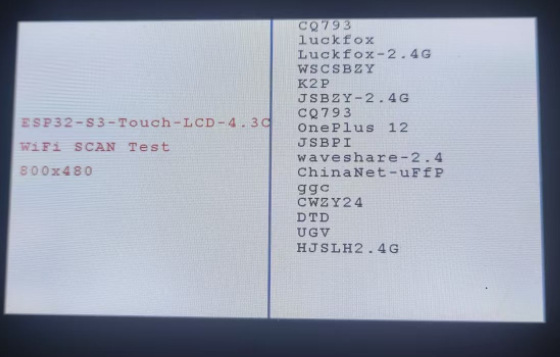
08_wifi_scan
本示例演示了在屏幕上显示扫描到的 WiFi 名称(无法显示中文 WiFi 名)。
硬件连接
- 使用 USB 线把板子接入电脑
代码
08_wifi_scan.ino
/*
* This example scans for nearby Wi-Fi signals and displays the
* Wi-Fi names (SSIDs) on the right side of the LCD screen.
*/
#include "src/rgb_lcd_port/rgb_lcd_port.h"              // Header for Waveshare RGB LCD driver
#include "src/rgb_lcd_port/gui_paint/gui_paint.h"       // Header for graphical drawing functions
#include "src/user_wifi/user_wifi.h"       // Header for Wi-Fi initialization and scanning functions

#define ROTATE ROTATE_0  // Set screen rotation: options are 0, 90, 180, 270 degrees

void setup() {
    Serial.begin(115200);  // Initialize the serial port for debugging

    // Check if PSRAM is available and functional
    if (psramFound()) {
        Serial.println("PSRAM is enabled and found!");
    } else {
        Serial.println("PSRAM not found or not enabled.");
    }
    delay(100);  // Short delay to allow initialization processes

    // Initialize Wi-Fi functionality
    wifi_scan_init();

    // Initialize I2C and the IO EXTENSION GPIO hardware interface
    DEV_I2C_Init();  // Start I2C communication
    IO_EXTENSION_Init();   // Configure the IO EXTENSION GPIO control chip

    // Initialize the RGB LCD display
    waveshare_esp32_s3_rgb_lcd_init();

    // Turn on the LCD backlight for visibility
    wavesahre_rgb_lcd_bl_on();
    // Uncomment the next line to turn off the backlight if needed
    // wavesahre_rgb_lcd_bl_off();

    // Allocate memory for the framebuffer (image buffer) in PSRAM
    UDOUBLE Imagesize = EXAMPLE_LCD_H_RES * EXAMPLE_LCD_V_RES * 2;  // Each pixel takes 2 bytes in RGB565 format
    UBYTE *BlackImage;
    if ((BlackImage = (UBYTE *)heap_caps_malloc(Imagesize, MALLOC_CAP_SPIRAM)) == NULL) {
        Serial.println("Failed to allocate memory for the framebuffer.");
        exit(0);  // Exit the program if memory allocation fails
    }

    // Initialize a new image canvas and set its background color
    Paint_NewImage(BlackImage, EXAMPLE_LCD_H_RES, EXAMPLE_LCD_V_RES, 0, WHITE);

    // Configure the canvas properties (scale and rotation)
    Paint_SetScale(65);       // Set the image scale
    Paint_SetRotate(ROTATE);  // Set the rotation angle (default 0 degrees)
    Paint_Clear(WHITE);       // Clear the canvas and fill it with a white background

    // Counter for Wi-Fi networks with Chinese SSIDs
    uint8_t chinese_num = 0;

    // Display static information on the screen
    Paint_DrawString_EN(10, 160, "ESP32-S3-Touch-LCD-4.3C", &Font24, RED, WHITE);  // Display title
    Paint_DrawString_EN(10, 200, "WiFi SCAN Test", &Font24, RED, WHITE);       // Display Wi-Fi scan test message
    Paint_DrawString_EN(10, 240, "800x480", &Font24, RED, WHITE);              // Display resolution
    Paint_DrawLine(400, 0, 400, 480, BLUE, DOT_PIXEL_2X2, LINE_STYLE_SOLID);   // Draw a vertical separator line
    Paint_DrawString_EN(440, 0, "Scanning now...", &Font24, BLACK, WHITE);     // Display scanning status
    wavesahre_rgb_lcd_display(BlackImage);  // Refresh the display to show the initial static messages

    // Clear the scanning message area
    Paint_ClearWindows(440, 0, 800, 25, WHITE);

    // Start Wi-Fi scanning and display the results
    wifi_scan();

    // Update the display with the new Wi-Fi scan results
    wavesahre_rgb_lcd_display(BlackImage);
}

void loop() {
    // Main loop remains empty for now
    // You can add additional functionality or updates to run continuously here
}
代码解释
-
setup():- 负责初始化所有通信接口和 LCD/Wi-Fi 硬件。准备图形环境,分配内存作为帧缓冲区。绘制静态 UI 并执行一次 Wi-Fi 扫描 (wifi_scan),将所有找到的网络 SSID 列表直接显示在 LCD 屏幕的右侧区域。
-
wifi_scan_init():- 初始化 Wi-Fi 硬件和配置。
-
wifi_scan():- 执行实际的 Wi-Fi 扫描,并将结果直接绘制到 LCD 屏幕上。
运行效果
-
烧录成功后,在屏幕上显示扫描到的 WiFi 名称。
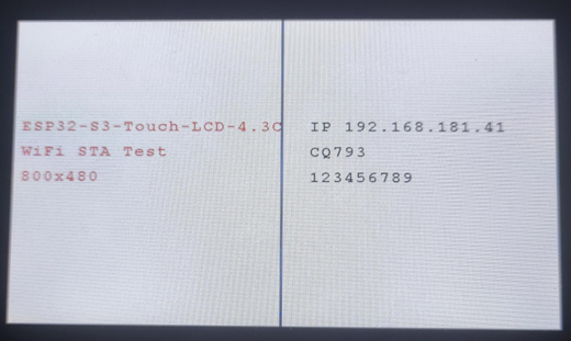
09_wifi_sta
本示例展示了如何使用屏幕显示连接热点的 IP 信息
硬件连接
- 使用 USB 线把板子接入电脑
代码
09_wifi_sta.ino
/*
* This example connects to an AP. Once connected, it displays
* the IP address, Wi-Fi name, and password. If the connection
* fails, it shows a connection failure message.
*/
#include "src/rgb_lcd_port/rgb_lcd_port.h"              // Header for Waveshare RGB LCD driver
#include "src/rgb_lcd_port/gui_paint/gui_paint.h"       // Header for graphical drawing functions
#include "src/user_wifi/user_wifi.h"       // Header for Wi-Fi initialization and scanning functions

#define USER_SSID "SSID"  // Wi-Fi SSID (network name)
#define USER_PASS "PASSWORD"  // Wi-Fi password

void setup() {
    Serial.begin(115200);  // Initialize the serial port for debugging

    // Check if PSRAM is available and functional
    if (psramFound()) {
        Serial.println("PSRAM is enabled and found!");
    } else {
        Serial.println("PSRAM not found or not enabled.");
    }
    delay(100);  // Short delay to allow initialization processes

    // Initialize I2C and the IO EXTENSION GPIO hardware interface
    DEV_I2C_Init();  // Start I2C communication
    IO_EXTENSION_Init();   // Configure the IO EXTENSION GPIO control chip

    // Initialize the RGB LCD display
    waveshare_esp32_s3_rgb_lcd_init();

    // Turn on the LCD backlight for visibility
    wavesahre_rgb_lcd_bl_on();
    // Uncomment the next line to turn off the backlight if needed
    // wavesahre_rgb_lcd_bl_off();

    // Allocate memory for the framebuffer (image buffer) in PSRAM
    UDOUBLE Imagesize = EXAMPLE_LCD_H_RES * EXAMPLE_LCD_V_RES * 2;  // Each pixel takes 2 bytes in RGB565 format
    UBYTE *BlackImage;
    if ((BlackImage = (UBYTE *)heap_caps_malloc(Imagesize, MALLOC_CAP_SPIRAM)) == NULL) {
        Serial.println("Failed to allocate memory for the framebuffer.");
        exit(0);  // Exit the program if memory allocation fails
    }

    // Initialize a new image canvas and set its background color
    Paint_NewImage(BlackImage, EXAMPLE_LCD_H_RES, EXAMPLE_LCD_V_RES, 0, WHITE);

    // Configure the canvas properties (scale and rotation)
    Paint_SetScale(65);       // Set the image scale
    Paint_Clear(WHITE);       // Clear the canvas and fill it with a white background

    // Display static information on the screen
    Paint_DrawString_EN(10, 160, "ESP32-S3-Touch-LCD-4.3C", &Font24, RED, WHITE);  // Display title
    Paint_DrawString_EN(10, 200, "WiFi STA Test", &Font24, RED, WHITE);       // Display Wi-Fi scan test message
    Paint_DrawString_EN(10, 240, "800x480", &Font24, RED, WHITE);              // Display resolution
    Paint_DrawLine(400, 0, 400, 480, BLUE, DOT_PIXEL_2X2, LINE_STYLE_SOLID);   // Draw a vertical separator line
    Paint_DrawString_EN(440, 160, "wifi connecting......", &Font24, BLACK, WHITE);     // Display scanning status
    wavesahre_rgb_lcd_display(BlackImage);  // Refresh the display to show the initial static messages

    // Clear the scanning message area
    Paint_ClearWindows(440, 160, 800, 185, WHITE);

    // Initialize Wi-Fi functionality and attempt to connect to the provided network
    wifi_sta_init(USER_SSID, USER_PASS);

    // Update the display with the new Wi-Fi scan results
    wavesahre_rgb_lcd_display(BlackImage);
}

void loop() {
    // Main loop remains empty for now
    // You can add additional functionality or updates to run continuously here
}
代码解释
-
setup():- 初始化所有通信接口和 LCD 硬件,并检查 PSRAM 状态。
- 分配帧缓冲区,初始化绘图画布,并绘制静态 UI(标题、分隔线和连接中提示)。
- 调用 wifi_sta_init(USER_SSID, USER_PASS) 尝试连接到预定义的无线接入点。
-
wifi_sta_init(USER_SSID, USER_PASS):- 初始化 Wi-Fi 模块并尝试以 Station 模式连接到指定的 SSID 和密码。其副作用是更新 LCD 上的连接状态。
运行效果
-
烧录成功后,连接成功或失败后更新屏幕右侧显示 IP 地址、Wi-Fi 名称等信息或连接失败消息。
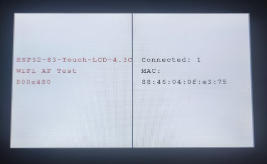
10_wifi_ap
本示例展示了如何使用屏幕显示热点的连接情况,会在屏幕上显示连接设备的 MAC 地址
硬件连接
- 使用 USB 线把板子接入电脑
代码
10_wifi_ap.ino
/*
* Create an Access Point (AP), and when devices connect,
* display their MAC addresses on the screen.
*/
#include "src/rgb_lcd_port/rgb_lcd_port.h"              // Header for Waveshare RGB LCD driver
#include "src/rgb_lcd_port/gui_paint/gui_paint.h"       // Header for graphical drawing functions
#include "src/user_wifi/user_wifi.h"       // Header for Wi-Fi initialization and scanning functions

#define USER_SSID "ESP32-S3-Touch-LCD-4.3C"  // Wi-Fi SSID (network name)
#define USER_PASS "66668888"  // Wi-Fi password

void setup() {
    Serial.begin(115200);  // Initialize the serial port for debugging

    // Check if PSRAM is available and functional
    if (psramFound()) {
        Serial.println("PSRAM is enabled and found!");
    } else {
        Serial.println("PSRAM not found or not enabled.");
    }
    delay(100);  // Short delay to allow initialization processes

    // Initialize I2C and the IO EXTENSION GPIO hardware interface
    DEV_I2C_Init();  // Start I2C communication
    IO_EXTENSION_Init();   // Configure the IO EXTENSION GPIO control chip

    // Initialize the RGB LCD display
    waveshare_esp32_s3_rgb_lcd_init();

    // Turn on the LCD backlight for visibility
    wavesahre_rgb_lcd_bl_on();
    // Uncomment the next line to turn off the backlight if needed
    // wavesahre_rgb_lcd_bl_off();

    // Allocate memory for the framebuffer (image buffer) in PSRAM
    UDOUBLE Imagesize = EXAMPLE_LCD_H_RES * EXAMPLE_LCD_V_RES * 2;  // Each pixel takes 2 bytes in RGB565 format
    UBYTE *BlackImage;
    if ((BlackImage = (UBYTE *)heap_caps_malloc(Imagesize, MALLOC_CAP_SPIRAM)) == NULL) {
        Serial.println("Failed to allocate memory for the framebuffer.");
        exit(0);  // Exit the program if memory allocation fails
    }

    // Initialize a new image canvas and set its background color
    Paint_NewImage(BlackImage, EXAMPLE_LCD_H_RES, EXAMPLE_LCD_V_RES, 0, WHITE);

    // Configure the canvas properties (scale and rotation)
    Paint_SetScale(65);       // Set the image scale
    Paint_Clear(WHITE);       // Clear the canvas and fill it with a white background

    // Display static information on the screen
    Paint_DrawString_EN(10, 160, "ESP32-S3-Touch-LCD-4.3C", &Font24, RED, WHITE);  // Display title
    Paint_DrawString_EN(10, 200, "WiFi AP Test", &Font24, RED, WHITE);       // Display Wi-Fi scan test message
    Paint_DrawString_EN(10, 240, "800x480", &Font24, RED, WHITE);              // Display resolution
    Paint_DrawLine(400, 0, 400, 480, BLUE, DOT_PIXEL_2X2, LINE_STYLE_SOLID);   // Draw a vertical separator line
    Paint_DrawString_EN(430, 160, "Connected: 0", &Font24, BLACK, WHITE);        // Display initial connection status
    wavesahre_rgb_lcd_display(BlackImage);  // Refresh the display to show the initial static messages

    // Initialize Wi-Fi functionality and attempt to connect to the provided network
    wifi_ap_init(USER_SSID, USER_PASS);

    // Update the display with the new Wi-Fi scan results
    wavesahre_rgb_lcd_display(BlackImage);
    static uint8_t connection_num = 0;
    while (1)
    {
      char mac[32];
      uint8_t n = wifi_ap_StationNum();
      if (connection_num != n)
      {
        char station_num[32];
        char station_mac[MAC_Addr_length];

        Paint_ClearWindows(430, 160, 800, 480, WHITE);  // Clear the section of the screen displaying the connection info
        snprintf(station_num, sizeof(station_num), "Connected: %d", n); // Format the number of connected stations
        Paint_DrawString_EN(430, 160, station_num, &Font24, BLACK, WHITE);  // Display the number of connected devices

        if (n == 0)
        {
            Serial.println("No device connected.");  // Log error if no devices are connected
        }
        else
        {
            Paint_DrawString_EN(430, 200 , "MAC:", &Font24, BLACK, WHITE);  // Label for MAC address
            for (int i = 0; i < n; i++) {
              wifi_ap_StationMac(station_mac, i);
              Paint_DrawString_EN(430, 240 + (i * 40), station_mac, &Font24, BLACK, WHITE);  // Display MAC address
              Serial.print("MAC Address: ");
              Serial.println(station_mac);
            }
            Serial.println("");
        }
        // Update the display with the new Wi-Fi scan results
        wavesahre_rgb_lcd_display(BlackImage);
        connection_num = n;
      }
      delay(100);
    }
}

void loop() {
    // Main loop remains empty for now
    // You can add additional functionality or updates to run continuously here

}
代码解释
-
setup():- 初始化所有硬件和图形环境,并将设备配置为无线接入点 (AP),使用预设的 SSID 和密码对外广播网络。
- 该函数包含一个无限循环:它持续检查连接到 AP 的设备数量。一旦检测到设备连接或断开,它会清空 屏幕区域,并更新显示当前连接数以及每个已连接设备的 MAC 地址列表。
-
wifi_ap_init(USER_SSID, USER_PASS):- 初始化 Wi-Fi 模块并将其配置为接入点 AP 模式,使用指定的网络名称和密码。
-
wifi_ap_StationNum():- 动态更新 LCD 屏幕右侧显示已连接设备数量
-
wifi_ap_StationMac(station_mac, i):- 显示每个连接设备的 MAC 地址
运行效果
-
烧录成功后,会显示 wifi 设备的连接数量和 MAC 地址。
11_speaker_microphone
本示例演示了通过触摸屏实现实现录音和播放功能。
硬件连接
- 使用 USB 线把板子接入电脑
代码
11_speaker_microphone.ino
/*
* Performs a five-point touch test and demonstrates basic usage of double buffering.
*/
#include "src/rgb_lcd_port/rgb_lcd_port.h"    // Header for Waveshare RGB LCD driver
#include "src/rgb_lcd_port/gui_paint/gui_paint.h"       // Header for graphical drawing functions
#include "src/gt911/gt911.h"           // Header for touch screen operations (GT911)
#include "src/user_sd/user_sd.h"           // SD card (not used directly here)
#include "src/speaker_microphone/codec_dev.h"    // Codec driver
#include "esp_check.h"    // Error handling macros

// Configuration macros
#define RECORD_TIME_SEC 5
#define BUFFER_SIZE (CODEC_DEFAULT_SAMPLE_RATE * RECORD_TIME_SEC * CODEC_DEFAULT_CHANNEL * (CODEC_DEFAULT_BIT_WIDTH / 8))

static int16_t *record_buffer = NULL;
UBYTE *BlackImage;

// Function to handle recording and playback
void play_or_pause(bool play)
{
    if (play)
    {
        // Recording logic
        Paint_DrawLine(390, 435, 390, 465, RED, DOT_PIXEL_2X2, LINE_STYLE_SOLID);
        Paint_DrawLine(410, 435, 410, 465, RED, DOT_PIXEL_2X2, LINE_STYLE_SOLID);
        Paint_DrawString_EN(200, 150, "Start recording...", &Font48, BLACK, WHITE);
        wavesahre_rgb_lcd_display(BlackImage);

        size_t total_bytes = 0;
        while (total_bytes < BUFFER_SIZE)
        {
            size_t bytes_read = 0;
            mic_i2s_read(record_buffer + total_bytes / 2,
                         BUFFER_SIZE - total_bytes,
                         &bytes_read, portMAX_DELAY);
            total_bytes += bytes_read;
        }

        Paint_Clear(WHITE);
        Paint_DrawLine(420, 450, 390, 435, RED, DOT_PIXEL_2X2, LINE_STYLE_SOLID);
        Paint_DrawLine(420, 450, 390, 465, RED, DOT_PIXEL_2X2, LINE_STYLE_SOLID);
        Paint_DrawLine(390, 435, 390, 465, RED, DOT_PIXEL_2X2, LINE_STYLE_SOLID);
        Paint_DrawString_EN(250, 150, "Recording done.", &Font48, BLACK, WHITE);
        wavesahre_rgb_lcd_display(BlackImage);
    }
    else
    {
        // Playback logic
        Paint_DrawLine(390, 435, 390, 465, RED, DOT_PIXEL_2X2, LINE_STYLE_SOLID);
        Paint_DrawLine(410, 435, 410, 465, RED, DOT_PIXEL_2X2, LINE_STYLE_SOLID);
        Paint_DrawString_EN(200, 150, "Start playing...", &Font48, BLACK, WHITE);
        wavesahre_rgb_lcd_display(BlackImage);

        size_t total_bytes = 0;
        while (total_bytes < BUFFER_SIZE)
        {
            size_t bytes_written = 0;
            speaker_i2s_write(record_buffer + total_bytes / 2,
                              BUFFER_SIZE - total_bytes,
                              &bytes_written, portMAX_DELAY);
            total_bytes += bytes_written;
        }

        Paint_Clear(WHITE);
        Paint_DrawLine(420, 450, 390, 435, RED, DOT_PIXEL_2X2, LINE_STYLE_SOLID);
        Paint_DrawLine(420, 450, 390, 465, RED, DOT_PIXEL_2X2, LINE_STYLE_SOLID);
        Paint_DrawLine(390, 435, 390, 465, RED, DOT_PIXEL_2X2, LINE_STYLE_SOLID);
        Paint_DrawString_EN(250, 150, "Playback done.", &Font48, BLACK, WHITE);
        wavesahre_rgb_lcd_display(BlackImage);
    }
}

void setup() {
    touch_gt911_point_t point_data;  // Structure to store touch point data

    Serial.begin(115200);
    DEV_I2C_Init();
    IO_EXTENSION_Init();
    // Initialize the GT911 touch screen controller
    touch_gt911_init(DEV_I2C_Get_Bus_Device());

    // Initialize the Waveshare ESP32-S3 RGB LCD
    waveshare_esp32_s3_rgb_lcd_init();
    // Turn on the LCD backlight
    wavesahre_rgb_lcd_bl_on();

    // Allocate LCD frame buffer
    UDOUBLE Imagesize = EXAMPLE_LCD_H_RES * EXAMPLE_LCD_V_RES * 2;
    BlackImage = (UBYTE *)malloc(Imagesize);
    if (!BlackImage)
    {
        Serial.println("Failed to allocate memory for frame buffer...");
        exit(0);
    }

    // Initialize the graphics canvas with buf2
    Paint_NewImage(BlackImage, EXAMPLE_LCD_H_RES, EXAMPLE_LCD_V_RES, 0, WHITE);

    // Set the scale for the graphical canvas
    Paint_SetScale(65);

    // Clear the canvas and fill it with a white background
    Paint_Clear(WHITE);

    // Draw initial red record button
    Paint_DrawCircle(405, 450, 15, RED, DOT_PIXEL_2X2, DRAW_FILL_FULL);
    Paint_DrawString_EN(100, 150, "Click to start recording", &Font48, BLACK, WHITE);
    wavesahre_rgb_lcd_display(BlackImage);

    // Initialize speaker codec
    codec_init();
    speaker_codec_volume_set(100, NULL);
    microphone_codec_gain_set(30, NULL);

    // Allocate memory for recording buffer
    record_buffer = (int16_t *)heap_caps_malloc(BUFFER_SIZE * sizeof(int16_t), MALLOC_CAP_SPIRAM | MALLOC_CAP_8BIT);
    if (!record_buffer)
    {
        Serial.println("Failed to allocate buffer");
        vTaskDelete(NULL);
        return;
    }

    // Touch handling loop
    static uint16_t prev_x;
    static uint16_t prev_y;
    bool is_playing = false;

    // Main application loop
    while (1)
    {
        point_data = touch_gt911_read_point(1);
        if (point_data.cnt == 1)
        {
            if (prev_x == point_data.x[0] && prev_y == point_data.y[0])
            {
                continue;
            }
            else if (point_data.x[0] > 390 && point_data.x[0] < 420 &&
                     point_data.y[0] > 420 && point_data.y[0] < 480)
            {
                Paint_Clear(WHITE);
                is_playing = !is_playing;
                play_or_pause(is_playing);

                prev_x = point_data.x[0];
                prev_y = point_data.y[0];
            }
        }
        delay(30);
    }
}

void loop() {
  // put your main code here, to run repeatedly:

}
代码解释
-
setup():- 该函数初始化所有硬件、触摸屏、LCD 和音频编解码器,分配音频缓冲区,然后进入一个无限循环,持续监测触摸操作,以在录音和播放录制的 5 秒音频之间切换。
-
play_or_pause(bool play):- 根据布尔参数切换程序状态:若为 true 则从麦克风读取 5 秒音频数据并存储到缓冲区(录音),若为 false 则从缓冲区读取数据并输出到扬声器(播放),并更新屏幕上的状态和图标。
-
codec_init():- 初始化音频编解码器 (codec_init) 并设置扬声器音量和麦克风增益,配置音频路径。
-
mic_i2s_read() / speaker_i2s_write():- 在 play_or_pause 函数内部调用,分别用于从麦克风读取音频数据和向扬声器写入音频数据。
运行效果
-
烧录成功后,当点击指定区域时切换录音/播放相应操作,实现录音和播放功能。
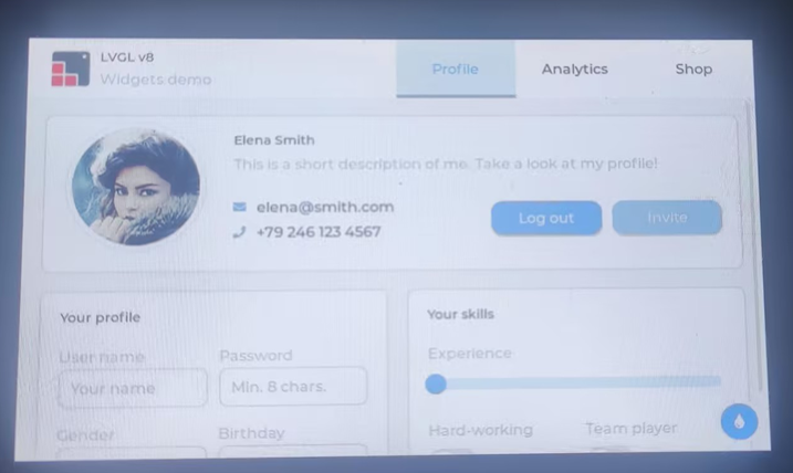
12_lvgl_transplant
本示例演示了 LVGL 移植。
硬件连接
- 使用 USB 线把板子接入电脑
代码
12_lvgl_transplant.ino
/*
* Ported LVGL 8.4 and display the official demo interface.
*/
#include "src/lvgl_port/lvgl_port.h"       // LVGL porting functions for integration
#include <demos/lv_demos.h>        // LVGL demo headers

void setup() {
    static esp_lcd_panel_handle_t panel_handle = NULL; // Declare a handle for the LCD panel
    static esp_lcd_touch_handle_t tp_handle = NULL;    // Declare a handle for the touch panel

    DEV_I2C_Init();
    IO_EXTENSION_Init();
    // Initialize the GT911 touch screen controller
    tp_handle = touch_gt911_init(DEV_I2C_Get_Bus_Device());

    // Initialize the Waveshare ESP32-S3 RGB LCD hardware
    panel_handle = waveshare_esp32_s3_rgb_lcd_init();

    // Turn on the LCD backlight
    wavesahre_rgb_lcd_bl_on();

    // Initialize LVGL with the panel and touch handles
    ESP_ERROR_CHECK(lvgl_port_init(panel_handle, tp_handle));

    Serial.println("Display LVGL demos");

    // Lock the mutex because LVGL APIs are not thread-safe
    if (lvgl_port_lock(-1)) {
        // Uncomment and run the desired demo functions here
        // lv_demo_stress();  // Stress test demo
        // lv_demo_benchmark(); // Benchmark demo
        // lv_demo_music();     // Music demo
        lv_demo_widgets();    // Widgets demo

        // Release the mutex after the demo execution
        lvgl_port_unlock();
    }
}

void loop() {
  // put your main code here, to run repeatedly:

}
代码解释
-
setup():- 它初始化所有硬件(I2C 总线、IO 扩展芯片)和 GT911 触摸屏,然后初始化 Waveshare RGB LCD 屏幕并开启背光。 核心功能:它将 LCD 和触摸屏句柄集成到 LVGL 图形库中 (lvgl_port_init),锁定 LVGL 互斥锁,然后启动 LVGL 官方的 Widgets 演示界面 (lv_demo_widgets)。
-
lv_demo_widgets():- 启动 LVGL 演示:加载并运行 LVGL 官方提供的 Widgets 示例界面。
运行效果
-
烧录成功后,显示 lvgl 的示例程序
其他说明
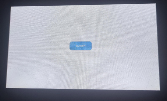
13_lvgl_btn
硬件连接
- 使用 USB 线把板子接入电脑
代码
13_lvgl_btn.ino
/*
* Creating a button using LVGL.
*/

#include "src/lvgl_port/lvgl_port.h"       // LVGL porting functions for integration
#include <demos/lv_demos.h>        // LVGL demo headers

static const char *TAG = "main";
/**
 * @brief  Event callback for button interactions
 * @param  *e: A pointer to `lv_event_t` containing event-related data
 * @return None
 */
static void btn_event_cb(lv_event_t * e)
{
    lv_event_code_t code = lv_event_get_code(e); // Retrieve the event code
    if (code == LV_EVENT_CLICKED) {
        Serial.println("Button Pressed.");
    }
}

/**
 * @brief  Creating a button using LVGL
 * @return None
 */
void lvgl_btn()
{
    // Create a button on the active screen
    lv_obj_t * btn = lv_btn_create(lv_scr_act());
    lv_obj_set_pos(btn, 10, 10);                      // Set the button's position
    lv_obj_set_size(btn, 120, 50);                    // Set the button's size
    lv_obj_align(btn, LV_ALIGN_CENTER, 0, 0);         // Align the button to the center of the screen

    // Add the event callback to handle button actions
    lv_obj_add_event_cb(btn, btn_event_cb, LV_EVENT_ALL, NULL);

    // Create a label and add it to the button
    lv_obj_t * label = lv_label_create(btn);
    lv_label_set_text(label, "Button");               // Set the label's text
    lv_obj_center(label);                             // Center the label within the button
}

void setup() {
    static esp_lcd_panel_handle_t panel_handle = NULL; // Declare a handle for the LCD panel
    static esp_lcd_touch_handle_t tp_handle = NULL;    // Declare a handle for the touch panel

    Serial.begin(115200);
    DEV_I2C_Init();
    IO_EXTENSION_Init();

    // Initialize the GT911 touch screen controller
    tp_handle = touch_gt911_init(DEV_I2C_Get_Bus_Device());

    // Initialize the Waveshare ESP32-S3 RGB LCD hardware
    panel_handle = waveshare_esp32_s3_rgb_lcd_init();

    // Turn on the LCD backlight
    wavesahre_rgb_lcd_bl_on();

    // Initialize LVGL with the panel and touch handles
    ESP_ERROR_CHECK(lvgl_port_init(panel_handle, tp_handle));

    Serial.println("Display LVGL demos");

    // Lock the mutex because LVGL APIs are not thread-safe
    if (lvgl_port_lock(-1)) {
         lvgl_btn();
        // Release the mutex after the demo execution
        lvgl_port_unlock();
    }
}

void loop() {
  // put your main code here, to run repeatedly:

}
代码解释
-
setup():- 初始化所有硬件(串口、I2C、IO 扩展、GT911 触摸屏)和 Waveshare RGB LCD 屏幕。 核心功能:它将 LCD 和触摸屏驱动集成到 LVGL 图形库中 (lvgl_port_init),然后锁定 LVGL 互斥锁,并调用 lvgl_btn() 在屏幕上创建并显示一个交互式按钮。
-
lvgl_btn():- 在 LVGL 当前活动屏幕的中心位置创建一个按钮对象。 设置按钮的大小、位置和标签文本 ("Button")。 将 btn_event_cb 回调函数绑定到按钮上,以响应用户的交互。
-
btn_event_cb(lv_event_t * e):- 当按钮被点击 (LV_EVENT_CLICKED) 时触发。 通过串口打印 "Button Pressed." 消息。
运行效果
-
烧录成功后,会在屏幕中间显示一个按钮,打开串口监视器,进行交互操作时,监视器会输出“Button Pressed.”。
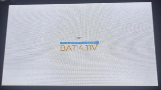
14_lvgl_slider
硬件连接
- 使用 USB 线把板子接入电脑
代码
14_lvgl_slider.ino
/*
 * Demonstrates an LVGL slider to control LED brightness and display battery voltage.
 */

#include "src/lvgl_port/lvgl_port.h"       // LVGL porting functions for integration
#include <demos/lv_demos.h>      // Optional: LVGL demo headers for extra examples

static lv_obj_t *label;          // Label to display slider value
static lv_obj_t *BAT_Label;      // Label to display battery voltage
char bat_v[20];                  // Buffer to store formatted battery voltage string

/**
 * @brief Callback function to update the battery voltage label.
 *
 * Called by an LVGL timer to refresh the battery voltage shown on the UI.
 *
 * @param timer Pointer to the LVGL timer object
 */
static void bat_cb(lv_timer_t * timer)
{
    lv_label_set_text(BAT_Label, bat_v); // Update the battery voltage label with latest value
}

/**
 * @brief Event callback for slider interaction.
 *
 * Triggered when the slider value changes.
 * Updates the label with the current value and adjusts LED brightness via PWM.
 *
 * @param e Pointer to the LVGL event descriptor
 */
static void slider_event_cb(lv_event_t * e)
{
    lv_obj_t *slider = lv_event_get_target(e); // Get the slider that triggered the event

    // Update the label with the slider's current value
    lv_label_set_text_fmt(label, "%" LV_PRId32, lv_slider_get_value(slider));

    // Set the PWM duty cycle based on slider value (inverted: 100 = off, 0 = full brightness)
    uint8_t duty = (100 - lv_slider_get_value(slider));
    IO_EXTENSION_Pwm_Output(duty); // Optional external PWM controller
}

/**
 * @brief Creates an LVGL slider to control LED brightness.
 *
 * Also creates a label to display slider value and another label to show battery voltage.
 */
void lvgl_slider(void)
{
    IO_EXTENSION_Pwm_Output(0); // Optional external control for brightness

    // Create the slider widget on the active LVGL screen
    lv_obj_t *slider = lv_slider_create(lv_scr_act());

    // Set slider dimensions and center it on screen
    lv_obj_set_width(slider, 200);
    lv_obj_center(slider);

    // Set initial slider value to 100 (LED off if active-low)
    lv_slider_set_value(slider, 100, LV_ANIM_OFF);

    // Attach the event callback for slider changes
    lv_obj_add_event_cb(slider, slider_event_cb, LV_EVENT_VALUE_CHANGED, NULL);

    // Create a label to display the current slider value
    label = lv_label_create(lv_scr_act());
    lv_label_set_text(label, "100"); // Initial label value
    lv_obj_align_to(label, slider, LV_ALIGN_OUT_TOP_MID, 0, -15); // Position above slider

    // Create a label for displaying battery voltage
    BAT_Label = lv_label_create(lv_scr_act());
    lv_obj_set_width(BAT_Label, LV_SIZE_CONTENT);
    lv_obj_set_height(BAT_Label, LV_SIZE_CONTENT);
    lv_obj_center(BAT_Label);
    lv_obj_set_y(BAT_Label, 30);
    lv_label_set_text(BAT_Label, "BAT:3.7V"); // Initial placeholder text

    // Style the battery label
    lv_obj_set_style_text_color(BAT_Label, lv_color_hex(0xFFA500), LV_PART_MAIN | LV_STATE_DEFAULT); // Orange text
    lv_obj_set_style_text_opa(BAT_Label, 255, LV_PART_MAIN | LV_STATE_DEFAULT);                     // Full opacity
    lv_obj_set_style_text_font(BAT_Label, &lv_font_montserrat_44, LV_PART_MAIN | LV_STATE_DEFAULT); // Large font
}

/**
 * @brief Main setup function.
 *
 * Initializes serial output, LCD panel, touch input, and LVGL.
 * Then creates the user interface with slider and labels.
 */
void setup() {
    static esp_lcd_panel_handle_t panel_handle = NULL; // LCD panel handle
    static esp_lcd_touch_handle_t tp_handle = NULL;    // Touch panel handle

    Serial.begin(115200);

    DEV_I2C_Init();
    IO_EXTENSION_Init();

    // Initialize GT911 capacitive touch controller
    tp_handle = touch_gt911_init(DEV_I2C_Get_Bus_Device());

    // Initialize Waveshare ESP32-S3 RGB LCD panel
    panel_handle = waveshare_esp32_s3_rgb_lcd_init();

    // Turn on the LCD backlight
    wavesahre_rgb_lcd_bl_on();

    // Initialize LVGL port with LCD and touch handles
    ESP_ERROR_CHECK(lvgl_port_init(panel_handle, tp_handle));

    Serial.println("Display LVGL demos");

    // Lock LVGL access, create UI, then unlock
    if (lvgl_port_lock(-1)) {
        lvgl_slider();  // Create UI elements
        lvgl_port_unlock();
    }
}

/**
 * @brief Main loop function.
 *
 * Continuously reads battery voltage via ADC and updates the label via a one-shot LVGL timer.
 */
void loop() {
    float value = 0; // Battery voltage accumulator

    // Take 10 ADC readings and average them to reduce noise
    for (int i = 0; i < 10; i++) {
        value += IO_EXTENSION_Adc_Input(); // Custom function to read ADC input
        delay(20); // Small delay between samples
    }
    value /= 10.0; // Compute average

    // Convert ADC value to voltage (assuming 10-bit ADC, 3.3V reference, and 3:1 voltage divider)
    value *= 3 * 3.3 / 1023.0;

    // Clamp voltage to max 4.2V for safe display
    if (value > 4.2) {
        value = 4.2;
    }

    // Format battery voltage string for display
    sprintf(bat_v, "BAT:%0.2fV", value);

    // Create a one-shot LVGL timer to update the label
    lv_timer_t *t = lv_timer_create(bat_cb, 100, NULL); // Trigger after 100 ms
    lv_timer_set_repeat_count(t, 1); // Run only once

    delay(100); // Wait before the next cycle
}
代码解释
-
setup():- 它初始化所有硬件和 Waveshare RGB LCD 屏幕。 将 LCD 和触摸屏驱动集成到 LVGL 图形库中 (lvgl_port_init),然后锁定 LVGL 互斥锁,并调用 lvgl_slider() 创建并显示包含滑块和电压标签的用户界面。
-
loop():- 循环读取 10 次获得的 ADC 值,并计算平均值以降低噪声。电压转换:将平均 ADC 值转换为实际电压。
-
lvgl_slider():- 在 LVGL 屏幕上创建主要的 滑块、显示滑块值的 数值标签,以及显示电池电压的 BAT 标签。同时,它将 IO 扩展的 PWM 输出初始化为 0 亮度,并将 slider_event_cb 绑定到滑块事件。
-
slider_event_cb(lv_event_t * e):- 当用户拖动滑块时触发。它更新滑块上方的数值标签,并根据滑块的当前值设置 IO 扩展芯片的 PWM 占空比 (IO_EXTENSION_Pwm_Output),从而控制 LED 亮度。
-
bat_cb(lv_timer_t * timer):- 由 loop() 函数创建的定时器触发。使用 lv_label_set_text 更新屏幕上的电池电压标签 (BAT_Label)。
运行效果
-
烧录成功后,显示滑动控件和电量信息,可以通过滑动组件控制图片亮度。
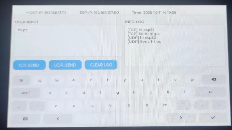
15_udp_tcp_ntp
硬件连接
- 使用 USB 线把板子接入电脑
代码
15_udp_tcp_ntp.ino
void setup() {
    static esp_lcd_panel_handle_t panel_handle = NULL;
    static esp_lcd_touch_handle_t tp_handle = NULL;

    Serial.begin(115200);
    DEV_I2C_Init();
    IO_EXTENSION_Init();

    // Initialize the GT911 touch screen controller
    tp_handle = touch_gt911_init(DEV_I2C_Get_Bus_Device());

    // Initialize the Waveshare ESP32-S3 RGB LCD hardware
    panel_handle = waveshare_esp32_s3_rgb_lcd_init();

    // Turn on the LCD backlight
    wavesahre_rgb_lcd_bl_on();

    // Initialize LVGL with the panel and touch handles
    ESP_ERROR_CHECK(lvgl_port_init(panel_handle, tp_handle));

    Serial.println("Display UI");

    // Lock the mutex because LVGL APIs are not thread-safe
    if (lvgl_port_lock(-1)) {
         ui_init();
         ui_log("System Initialized. Waiting for WiFi...");
         lvgl_port_unlock();
    }

    // Auto-connect task
    xTaskCreate(wifi_connect_task, "WiFiConnect", 8192, NULL, 3, &ntpTaskHandle);
}

void loop() {
  // Update time
  struct tm timeinfo;
  if (WiFi.status() == WL_CONNECTED && getLocalTime(&timeinfo)) {
    char buf[64];
    strftime(buf, sizeof(buf), "%Y-%m-%d %H:%M:%S", &timeinfo);
    if (lvgl_port_lock(100)) {
      lv_label_set_text_fmt(label_time, "Time: %s", buf);
      lvgl_port_unlock();
    }
  }
  delay(1000);
}
代码解释
-
setup():- 初始化串口、I2C、IO 扩展、触摸屏和 LCD 硬件,并初始化 LVGL 图形库。接着调用
ui_init()加载界面,并创建wifi_connect_task任务进行后台联网与对时。
- 初始化串口、I2C、IO 扩展、触摸屏和 LCD 硬件,并初始化 LVGL 图形库。接着调用
-
loop():- 定时获取系统本地时间,并使用
lvgl_port_lock确保线程安全地更新屏幕上的时间显示标签。
- 定时获取系统本地时间,并使用
-
wifi_connect_task():- 负责连接 WiFi 网络,并在联网成功后通过 NTP 服务器同步系统时钟。
运行效果
-
烧录成功后,屏幕显示系统初始化信息,联网成功后将通过 NTP 获取并实时刷新显示当前日期与时间。